Continuous springy beamsby Russ Elliott Contents
Note: This page addresses longitudinal settings for the fulcrum points of CSBs. For suggestions on the setting out of the vertical position of the fixed fulcrums on a CSB chassis, see this page. Related pages
|
|
|||||||||||||||
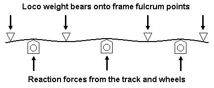
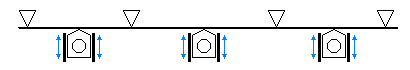
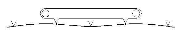
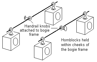
IntroductionA continuous springy beam, or perhaps more accurately a contiguous springy beam, is a single spring spanning multiple, typically more than two, axles. The CSB is on each side of a chassis. Its purpose is to provide a reasonably equal deflection, and hence force, to all the driving wheels when a loco is sitting, statically, on flat track. Dynamically, on undulating track, the forces on the wheels will change and vary, just like the prototype. The beam provides a degree of equalisation between the axle forces. Like any springs, a CSB decouples the mass of the loco body and chassis from our rigid track, because it slowly absorbs and dissipates the energies caused by bumps and dips in the track. (This is in contrast to a rigid compensation beam, which transmits dips and bumps in the track abruptly and immediately to the chassis.)The use of a continuous springy beam in a chassis or drive bogie has the practical advantage of being changeable, so that an optimum ride characteristic can be achieved. Springs are also an excellent way of minimising the effects of eccentric wheels on a chassis. The way in which the continuous beam bends is significantly different compared to the use of separate springy beam sections for each hornblock. Although in both cases there is no constraint on the rotation of the beam about the fulcrum pivot points, the deflection of a hornblock in the case of the continuous springy beam influences the deflection of the adjacent one, and therefore a degree of longitudinal equalisation is present. The axle deflections produced in a CSB depend on the spacing and relationship of the frame and axle fulcrum points, the strength of the beam, the overall weight of the loco, and where the centre of gravity of the loco is. To allow rotation of the beam about the fulcrum pivot points, the beam is not constrained along its longitudinal axis by any additional longitudinal force, i.e. it is not fixed to any of the fulcrum pivot points nor is it fixed to the chassis. In the CSBs shown on this page, there are no additional rotational moments applied to the outermost fulcrum points. Although the principle of using a single wire across several hornblocks is not new, there being a number of locomotives marketed in the USA in the late 1940s, and in the UK in the 1950s, with tension-assisted devices, Ted Scannell is regarded (from a CLAG perspective) as having the brainwave of making a spring beam continuous over two (and later, three, etc) axles. The first implementation of this type of continuous spring beam is thought to have been in Bill Bedford's coach bogies. |
|
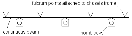
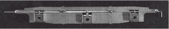
| Although the diagrams on this page show overslung CSBs, they can of course be implemented in underslung mode. | .gif) |
Spreadsheet toolsThe following downloadable Excel spreadsheets are available for determining the optimum combination of fulcrum position points, beam diameter and beam deflection:
These spreadsheets may be updated from time to time. I am indebted to Roger Wyatt, Will Litchfield and Alan Turner for producing these tools. |
Spreadsheet notes:
Roger Wyatt's spreadsheet (and Will Litchfield's expanded version of it) analyses the continuous beam situation by turning the chassis upsidedown, and uses the iterative 'Moment distribution method'. Please note as from November 2011 the above spreadsheets use axle weight inputs (rather than wheel weights) for consistency with each other and consistency with Alan Turner's spreadsheet.
Alan Turner's spreadsheet uses a more modern finite element method in solving a stiffness matrix. The spreadsheets provide their primary purpose, namely to establish the fulcrum point positions. Beyond that, both forms of spreadsheet have their advantages and disadvantages. Alan Turner's gives a direct indication of the loading of each axle for the chosen deflection value, whereas deriving those loadings is a longer iterative process in the moment-distribution spreadsheet. From the latter however can be derived the deflection differences (and hence loading differences, if desired) for situations where individual axles are each deflected by different amounts, which cannot be input in Alan Turners' spreadsheet. Alan Turner's spreadsheet allows the input of a centre of gravity position, and can show the effect of it being moved. |
Some worked examplesNotes:
|
If you want a CSB plot for a particular wheelbase or chassis, please feel free to contact me. Please provide the wheelbase dimensions. |
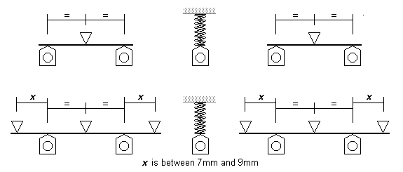
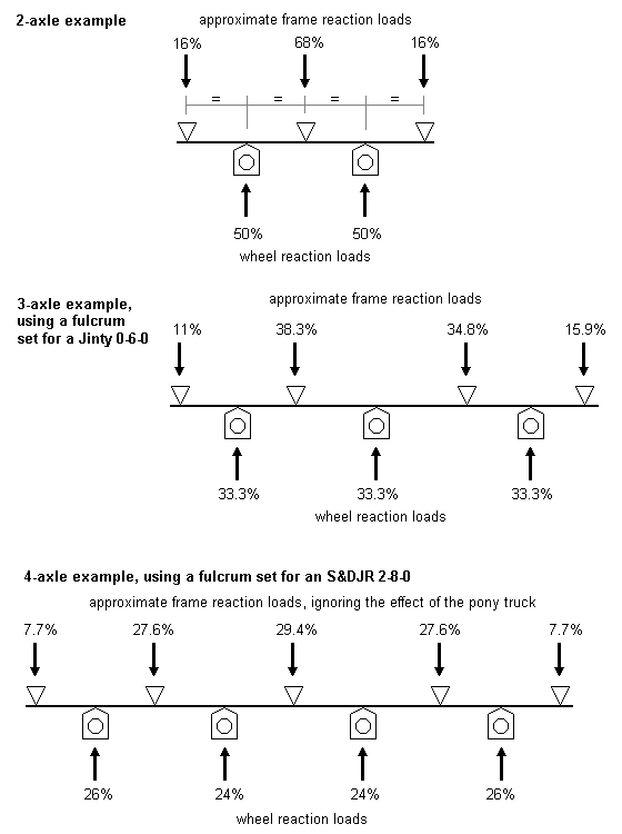
| Symmetrical 2-axle case For the symmetrical 3-fulcrum 2-axle case, deflections and axle loads will be equal for any axle positions symmetrically positioned about a centrally-located fulcrum. Within the limits reasonably imposed on the position of the outer fulcrums, the position at which the deflection of the beam is maximised is shown in the diagram. | 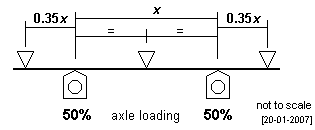 |
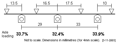
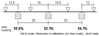
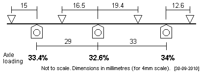
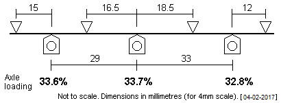
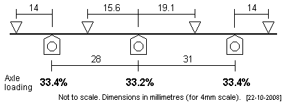
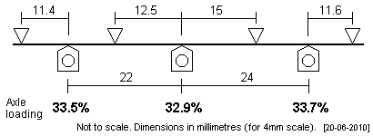
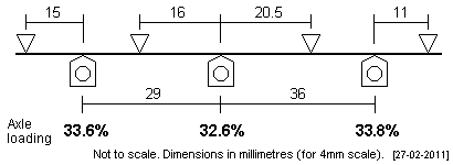
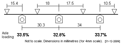
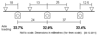
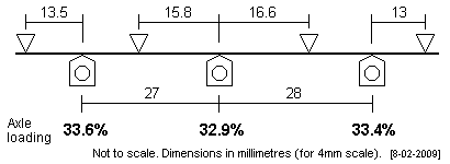
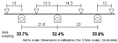
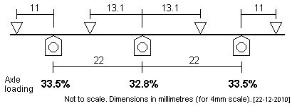
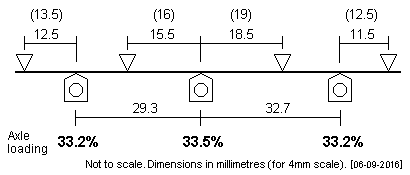
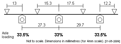
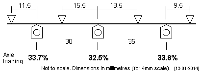
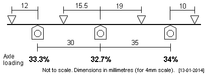
| Symmetrical 3-axle case There are many solutions* to the 4-fulcrum 3-axle configuration, and the adjacent diagrams show examples of the model for the symmetrically-spaced, symmetrically-weighted, 3-axle case.
Some of these 3-axle examples have a slightly reduced springrate on the middle axle, to ensure good pitch stability. * strictly speaking, an infinite number of solutions |
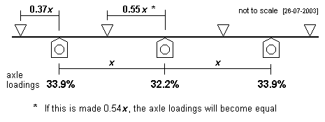 In this example, the ratio of the middle span length (1.1x) to the outer span length (0.82x) is 1.34:1 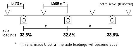 In this example, the ratio of the middle span length (1.138x) to the outer span length (0.854x) is 1.33:1 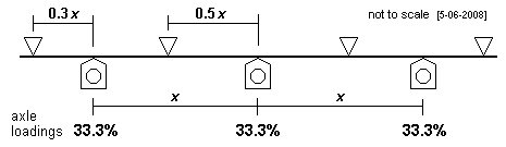 In this example, the ratio of the middle span length (x) to the outer span length (0.8x) is 1.25:1 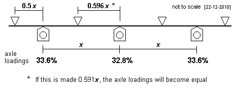 In this example, the ratio of the middle span length (1.19x) to the outer span length (0.9x) is approximately 1.32:1 |
| Examples of symmetrical 3-axle cases | ||||||||||||||||||
| Taking the example of the driving wheels of a Drummond F13 Paddlebox 4-6-0 with a wheelbase of 6'7" + 6'7", different sets of fulcrum points can be derived. The axles are equally loaded for these sets of fulcrum points. |
|
 |
||||||||||||||||
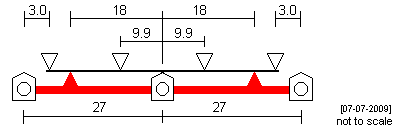
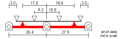
| Another more common example of a symmetrical wheelbase – a 6'6" + 6'6" tender. A selection of fulcrum point sets is given to cater for different frame length space and constraints from frame spacers, etc. The axles are loaded equally for these sets of fulcrum points. |
|
 |
||||||||||||||||
The shorter outer spans will increase the potential errors in the system owing to the finite length of the frame fulcrums; the use of the longer outer spans will reduce these potential errors and enable the use of a slightly greater beam diameter. |
||||||||||||||||||
|
Pannier (also Dean/Collett Goods) The common Churchward/Collett large Pannier 0-6-0 has a wheelbase of 7'3" + 8'3". The frontmost fulcrum point has been positioned to avoid the front axle brake hangar pivot.
Several sets of plots are given, illustrating how different span lengths can keep axle loads reasonably equitable. All of these plots, except for the last, intentionally lighten the middle axle slightly. |
|
| The second and third plots have a more symmetrical rear axle span, the second plot retaining the same axle load distribution as the first plot, whilst the third plot relaxes the middle axle further. |

|
|
|
| The fourth plot extends the outermost fulcrum points further. |
|
| The fifth plot for this wheelbase caters for the frame spacers in the High Level Models Collett Goods (2251 Class) chassis. |
|
|
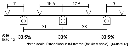
Collett standard The common Collett wheelbase for the majority of his larger 6-coupled engines was 7' + 7'9". The plot loads the axles equally. |
|
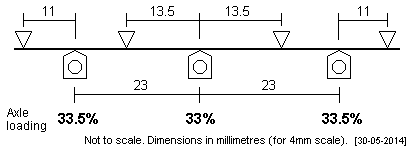
| 56xx This large tank has a wheelbase of 7'3" + 8'. The plot loads the axles equally. |

|
|
45xx This small prairie tank has a very short driver wheelbase of 5'6" + 6'.
The comparative shortness of the CSB exacerbates the criticality of the fulcrum widths. |
|
| LNER J50, N2, V1/V3 etc A common Gresley wheelbase was 7'3" + 9'0". |
|
| LNER 4200g group standard tender This tender has an asymmetrical wheelbase of 7'3" + 6'3". |

|
| GER N7 This wheelbase was 7'6" + 8'9", and the plot is similar to the LNER V1/V3. |

|
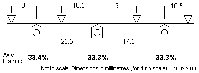
| GER J15 This wheelbase was 7'7" + 8'6". In this loco, there is not much room between the rear driver and the end of the frame, and the rearmost fulcrum point has been pulled in to allow a feasible fulcrum point implementation. |
|
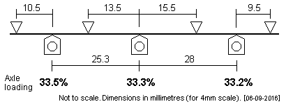
| LNER J65 This wheelbase was 6'4" + 7'0". Alongside is the plot chosen by Will Litchfield for his loco build. |
|
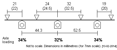
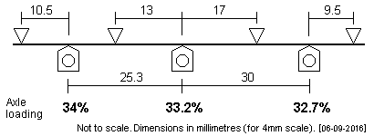
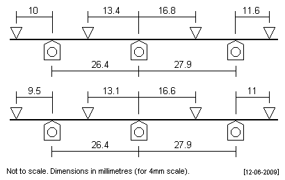
| LNER J67/J68/J69 This wheelbase was 6'4" + 7'6". Two 7mm scale plots are shown, an alternative set of frame fulcrum points being given in brackets. |
|
| In 4mm scale, Will Litchfield has adopted the plot alongside for his J69. |
|
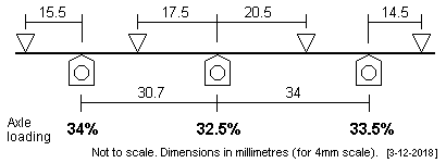
| LNER J72 0-6-0 This small tank loco has a prototype wheelbase of 6'8" + 7'. |

|
| LNER J77 0-6-0 This tank loco has a prototype wheelbase of 7'8" + 8'6", so is very similar to the J15, but in this case, there is no restriction on space at the rear of the frame. |
|
| LNER J94 0-6-0 This tank loco has a prototype wheelbase of 5'9" + 5'3". |
|
|
GER E4 The prototype axle weights of this 7'9" + 8'9" wheelbase 2-4-0 made it intentionally nose heavy, and equality of driver weights was achieved only in the forward direction and under the effect of drawbar pull, which has the effect of shifting the the loco's CofG backward. The outer fulcrum positions have been adjusted to provide a reasonable compromise setting between the light engine and loaded engine states, although CofG achievement (directly over the front driver) remains fussy.
In the context of the small deflection of the beam, setting the height differential between the hornblocks of the carrying axle and the coupled axles is difficult, and there are simpler solutions for these wheelbases not involving a CSB over all axles. |
|
| L&Y Class 23 saddle tank This large 0-6-0ST has a near-symmetrical wheelbase of 7'3" + 7'9". |

|
| Midland 7' + 7'4" A 7mm plot for a Midland 1F 0-6-0T |
|
|
Midland 8' + 8'6" A common Midland/LMS wheelbase was 8' + 8'6".
An alternative plot is given for a longer beam, which will enable a slightly thicker beam diameter to be used. |

|
| LMS jackshaft shunter This has a highly asymmetric wheelbase of 6' + 9'3" owing to the presence of a jackshaft drive between the centre and rear axles. |
|
| Hudswell Clarke 6'3" + 7' Small industrial tank locos tend to have relatively short wheelbases compared to the overall loco length. There is therefore usually enough room for the outermost fulcrum points to have an adequate distance from their respective axles. |

|
|
Black 5 The LMS Black 5 has two driver wheelbase variants: 7' + 8', and 7' + 8'4". The front fulcrum point is close to the front brake hangar, but Black 5 brake hangars are pivotted at about axle datum height, and the CSB axis is sufficiently above the axle datum to avoid the brake hangar. The rearmost fulcrum point will probably clash with the frame spacer in some kits in this area. |


|
| Standard Class 5 The Standard Class 5 has a wheelbase of 7' + 8'6". The plot is similar to the longer Black 5 variant. |

|
| Ivatt 2MT The Ivatt 2MT Mogul has a driving wheelbase of 6'9" + 7'. |
|
|
3.5mm scale continental 0-6-0 This small tank loco has a prototype wheelbase of 1900mm + 2000mm, with plenty of room fore and aft of the front and rear axles respectively for fulcrum location. The plots unloads the centre axle more than is usual, since the builder intends to drive on the middle axle, and the comparatively high extent of the centre axle unloading is to make some allowance for the extra unsprung weight on that axle, namely a proportion of the weight of the motor/gearbox. For a small-ish 3.5mm scale tank engine, the unsprung proportion of the weight of the motor/gearbox is going to be significant in relation to the total weight. For an all-up weight of between 150g and 180g, I suggest using 10 or 11 thou steel wire for the CSB. |
|
|
SE&CR P 0-6-0 This very small tank loco has a symmetrical prototype wheelbase of 5'6" + 5'6". In this example of a short wheelbase, fulcrum positions are critical, but the outer spans have been extended in an effort to lessen the potential marking out error. |
|
| SE&CR R 0-6-0 This small tank loco has a prototype wheelbase of 7'4" + 8'2". The plot loads the axles equally, or very nearly so. An alternative set of frame fulcrum point spacings is given in brackets. |
|
|
LSWR G6 0-6-0 This small tank loco has a prototype wheelbase of 6'10" + 7'5".
The overall weight of this loco is intended to be 220g, and at this weight a 0.013" diameter steel CSB will give 0.5mm deflection on the axles. |
|
| CR Class 782 0-6-0 This tank loco has a prototype wheelbase of 7'6" + 8'9". The GER N7 has an identical wheelbase, but its plot (given above) is unsuitable because of the location of the front frame spacer, and thus a shorter overall plot is more suitable for the smaller CR tank loco. Two plots are given here. |
|
| CR Class 812 0-6-0 This tender loco has a prototype wheelbase of 7'9" + 9'. Adjacent is the plot chosen by Steve Duckworth for his build. |
|
| North London Railway 0-6-0T The short symmetrical wheelbase on this tank loco was 5'9" + 5'9". |
|
| Hawthorn Leslie 14" 0-6-0ST The short wheelbase on this tank loco was 5'6" + 5'. |

|
| Kitson 'Consett A class' 0-6-0T The suggested plot for this short wheelbase (6'4.5" + 4'4.5") tank is tight because of the closeness of the rear two axles and the asymmetry of the wheelbase. |
|
|
Class 59 bogie This 3-axle bogie has a prototype wheelbase of 6'7 ¼" + 6'11 ¾".
The frame length forward of the front axle of the bogie is restricted, and alternative plots are offered. The plots load the axles equally. For an overall loco weight of c 500g, a 0.013" diameter steel spring will give nearly 0.5mm axle deflection, 0.012" will give just over 0.6mm deflection, and 0.011" will give approx 0.85mm deflection. An alternative, but very different, 'inside the wheelbase CSB', is given further down this page. |
|
|
Stanier 8F Two plots are shown for the driving axles of this 2-8-0 engine, which has a 5'6" + 5'6" + 6'3" driving axle wheelbase. The second (lower) plot has the end supports more comfortably placed. In either case, the loading on the axles is very similar.
The centre of gravity has been assumed to give a symmetrical loading over the group of the 4 driving axles: in practice, the centre of gravity will need to be somewhat in advance of this point, as the pony truck will need to carry a proportion (comparatively small) of the loco weight, but the drawbar pull effect will bring the centre of gravity backwards somewhat to restore the loading close to the optimum state assumed by this plot. |
|
| S&DJR 7F 2-8-0 This loco has an 6' + 5'6" + 6' driving axle wheelbase. The plot makes the middle two axles slightly softer than the outer axles. If the 10mm dimensions are increased to 10.5mm, the axles will be loaded equally. |
|
| WD 2-8-0 This loco has an 5'3" + 5'3" + 5'9" driving axle wheelbase. |
|
| GWR 42xx and 72xx These large tanks have a coupled wheelbase of 7' + 6' + 7'. The plot makes the axles equally weighted. If the 9mm dimensions are reduced to 8.5mm, the middle axles will become slightly softer. |
|
| GWR 28xx/38xx These large freight engines have a coupled wheelbase of 5'5" + 5'5" + 6'. The suggested plot makes the axles equally weighted, to all intents and purposes. |

|
| LNER A1/A2/A4 8-wheel tenders These 8-wheeled tender have a 5'3" + 5'6" + 5'3" wheelbase. The plot makes the two inner axles slightly softer than the outermost ones. The outermost fulcrum points have been set at a reasonable distance from the outer axles, although the outermost axle deflections are some distance from the peaks of their deflection curves, so a reasonable degree of verticality in the outermost (hornblock-less) carriers is necessary to keep their interface with the beam curve to the intended longitudinal position. |
|
| LNWR G1/G2 This 4-coupled wheelbase is symmetrical, 5'9" + 5'9" + 5'9". Although the outermost axle deflections are some distance from the peaks of their deflection curves, the outermost fulcrum points have been set at a generous distance from the outer axles in order to reduce the potential errors arising from the marking out and positioning, and the error arising from the finite length of the fulcrum point itself. |
|
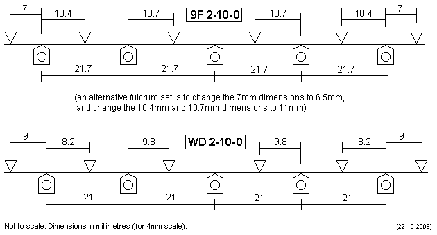
| 10-coupled locos The prototype BR Standard 9F 2-10-0 has a 5'5" + 5'5" + 5'5" + 5'5" driving axle wheelbase, and the WD 2-10-0 has driving axles spaced at 5'3". It is debatable whether a CSB is the optimum solution for a 10-coupled; the outermost fulcrum points can be close to their axles, and it is uncertain whether a CSB would give enough axle deflection unless a small diameter beam is used. The frictional effects over the many fulcrum points could become problematic. |
|
| A larger and more predictable deflection would be given by two pairs of equalising springy beams, one pair between the front pair of drivers and other pair between the rear pair of drivers, with a separate (cantilever beam or coil) spring on the middle driver. CSBs can be used instead of these springy equalising beams – the springing characteristic will be equivalent. |
 |
Relationship between load distribution and deflection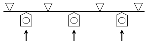
|
For discrete springs, deflection is directly proportional to the load. In a typical CSB, where a middle axle can be deliberately unloaded slightly for the purposes of ensuring good pitch stability, the deflection differential set up for the middle axle relative to the outer ones will not be in direct proportion to the load differential of the axles when the wheels are sitting on level track under equal deflection. This is because, when the middle axle is relaxed slightly to sit on the track, i.e. its deflection becomes the same as the outer axles, the load input conditions of the initial setup state no longer apply, and the load relationships throughout the beam and the frame change.
Typically, for the 3-axle case, if the middle axle deflection is set to be x% larger than the outer ones for a given input setup load, and where x < 15%, when the middle axle relaxes to sit on the track under the same deflection as the outer axles, the middle axle load is in the region of (x ∕ 3)% less (in relative terms) than the outer ones. In terms of absolute percentages of axle loads, this relative difference translates into the region of (x ∕ 6)% or even less. This is a roundabout way of saying that, once the fulcrum positions are at or near their optimum positions, the axle load distribution is very tolerant of small departures from those positions. |
Effect of moving fulcrum points on springrate
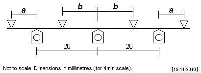
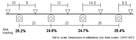
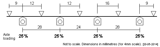
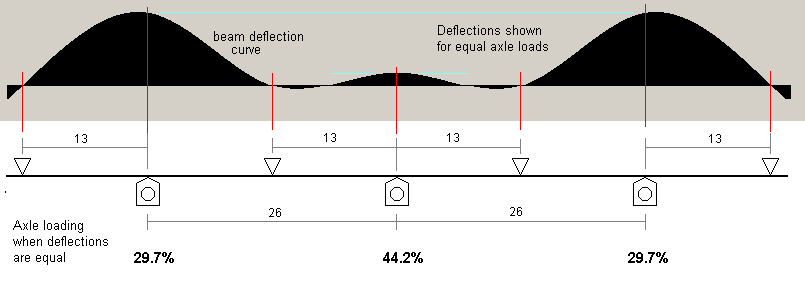
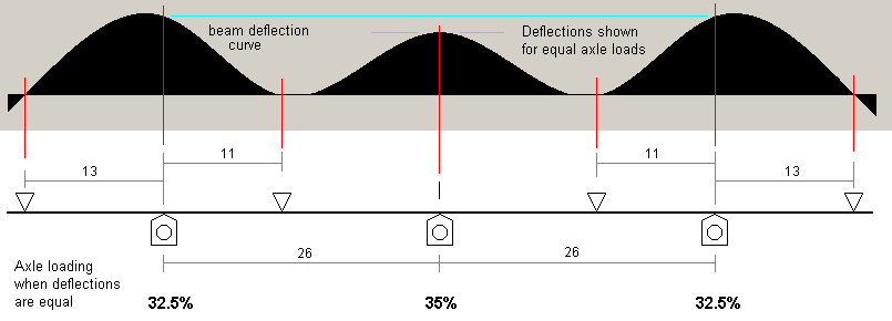
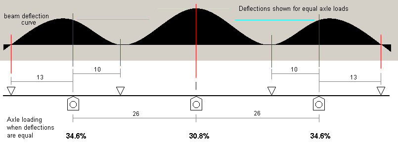
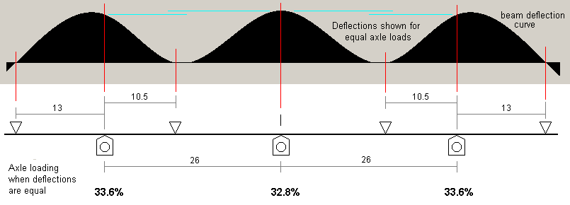
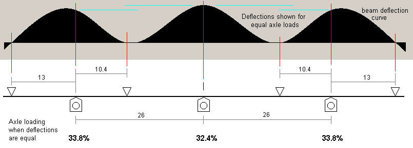
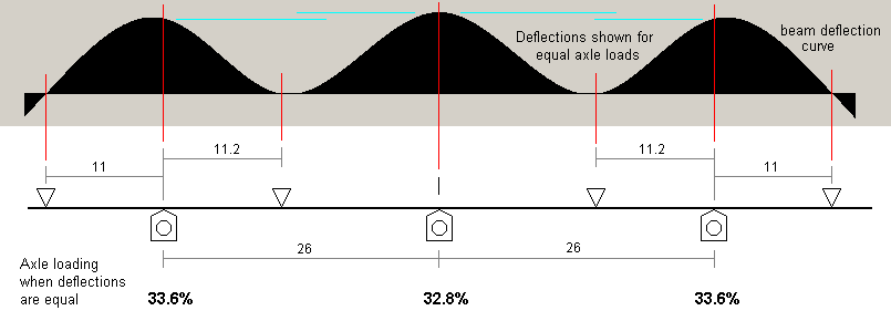
Variations in the positioning of fulcrum points can have dramatic implications for springrate. The following diagrams illustrate comparative deflections and axle loads in an example of a symmetrically-weighted 3-axle symmetrical wheelbase of 6'6" + 6'6" (26mm + 26mm).
The deflection curves shown in the following diagrams show the effect on deflection of equal forces applied at each axle. The axle loading values given apply when the axles are equally deflected, as would be the case when sitting on flat track.
The first deflection plot has the inner fulcrum points midway between their respective axles, and with the outer fulcrum points set 13mm outside the outer axles. The ratio of the middle span length to the outer span length is 1:1. This configuration makes the middle axle deflect a lot less less than the outer axles if the axles are equally loaded, in this case by a factor of 5.5. Such a setting for a middle axle would make it far too strong, and the chassis would porpoise.
|
|
||
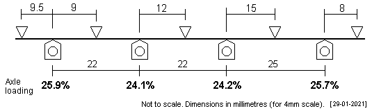
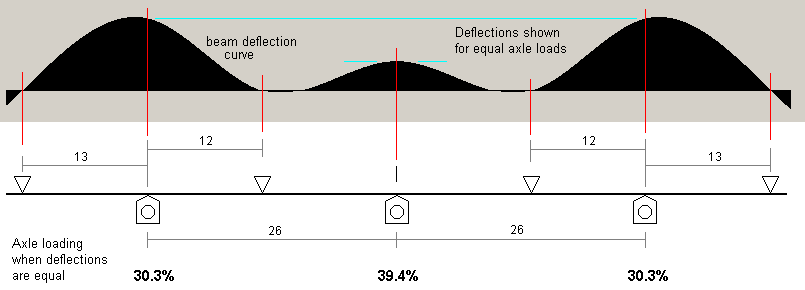
The second deflection plot increases the middle span by 2mm. The ratio of the middle span length to the outer span length is 1.12:1. For a given force, the deflections of the outer axles are still nearly 2.5 times the deflection of the middle axle, which is therefore still too strong. Note as the middle span increases, the location of the maximum deflection of the outer spans becomes further away from the axle.
|
|
||
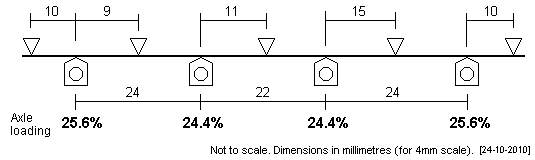
The third deflection plot increases the middle span by a further 2mm compared to the previous configuration. The ratio of the middle span length to the outer span length is 1.25:1. Here, the deflections of the outer axles are 25% more than the deflection of the middle axle for a given force, and whilst the axle loading is now more equitable when the wheels are sitting on the track under equal deflection, there is still a possibility of pitch instability on uneven track.
|
|
||
By increasing the middle span by a further 2mm, to 32mm, the deflection characteristic has inverted, with the middle axle deflection for a given force now nearly 46% more than the outer axles. The ratio of the middle span length to the outer span length is 1.39:1. This middle span dimension is more than we want for an equitable loading of the axles.
|
|
||
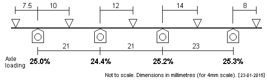
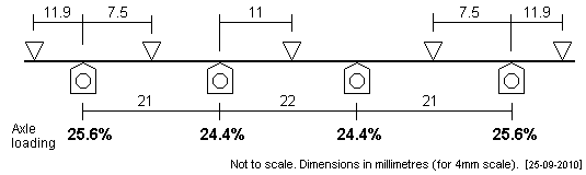
Setting the middle span to 31mm produces a desirable deflection characteristic, with all axles deflecting reasonably equal, and with the middle axle marginally softer than the outer axles. The ratio of the middle span length to the outer span length is 1.32:1.
|
|
||
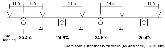
The final deflection characteristic is included to show the effect on load sensitivity of the inner fulcrum point positions. Compared to the middle span length of 31.2mm in the previous configuration, the effect on the axle loads can be seen if the middle span length is increased by a further 0.2mm. In context however, once the fulcrum positions are near to their optimum positions, small departures from those positions will have a comparatively small effect on axle load distribution. The ratio of the middle span length to the outer span length here is 1.33:1.
|
|
In the above cases, where the outermost fulcrum points are kept at the same positions, it can be seen that lengthening the middle span will increasingly shift the outer axle deflections away from the point of maximum deflection of that part of the beam. This is not necessarily a drawback, but a better characteristic, utilising nearer the maximum deflection of the outer span, can be achieved by pulling in the outermost fulcrum points and decreasing the middle span, as in the following example, which retains a ratio of the middle span length to the outer span length of 1.33:1.
| From this plot can be derived another general case for the symmetrical 3-axle wheelbase: | |
CSBs without outer fulcrums
All the above plots have outer fulcrums. The deflection of all the axles is therefore constrained by a similar principle, i.e. that there are counterbalancing moments either side of each axle fulcrum, and with the slope of the curve of the CSB at each axle ideally being near zero. For some 3-axle drive bogies however, there is not always adequate length to have outer fulcrums. In theory, it is possible to have only two fulcrum points for a 3-axle case. The 2-fulcrum model for the 3-axle case is where the outer axles are deflected by the principle of the free cantilever. The deflection characteristic of the outer axles is therefore radically different compared to the case where outer fulcrums are present. As can be seen above for the outer fulcrum model, slight movements of fulcrum points have dramatic implications for springrate; these implications become acute where no outer fulcrums are present, because of the exceptionally high sensitivity of the equalisation.
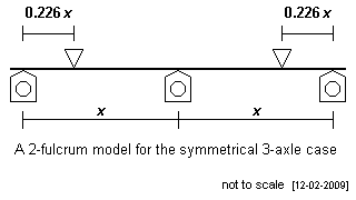
The diagram adjacent shows the general case for the equal loading of axles in the symmetrical 3-axle case.
In the context of an example of a 27mm + 27mm bogie (6'9" + 6'9" in 4mm scale), moving each of the fulcrum points 0.1mm outwards leads to a situation where the middle axle deflection is 33% greater than the outer ones. Conversely, moving each of the fulcrum points 0.1mm inwards leads to the middle axle deflection being 31% less than the outer ones. Although these percentage changes will be a lot less if expressed in absolute axle load terms, the positioning of these fulcrum points is therefore exceptionally critical and arguably far too sensitive, given the practical constraints that real fulcrum points have finite widths, of up to an order of magnitude greater than 0.1mm.
I draw attention to the possiblity of CSBs without outer fulcrums for the 3-axle case only to dismiss them from further consideration.
CSBs inside the total wheelbase
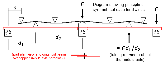
The first constraint in the CSB design is c, the clearance needed from the end of the CSB to the outer axle bearings/hornblocks.
The next condition is to choose a lever ratio for the rigid beams: if F is the force we want on each axle, the reaction force needed to balance the rigid beam at the point where it bears up against the CSB is Fd1 ∕ d2 This greater reaction force on the outer spans requires a different set of CSB inner fulcrum point positions (compared to a conventional CSB) design to keep the axle deflections consistent. Typically, the relationship of d1 and d2 will be in the region of 1.5d2 = d1 The CSB length is 2(d1 – c) |
For some bogies, frame lengths forward of the front axle and rearward of the rear axle are often restricted, making the incorporation of fulcrum points outside the wheelbase difficult or impossible. It is feasible to bring the CSB's outer fulcrum points inside the wheelbase, and use two separate rigid beams to link each outer axle to the middle axle. Each rigid beam impinges up against the CSB at a chosen point along the length of the rigid beam.
The CSB length is short. The longitudinal distance between between the outer fulcrum and the rigid beam fulcrum point is extremely short. Given the finite width of fulcrums, the loading errors are therefore potentially large.
For 3-axle drive bogies of between 70g and 80g per axle weight, 0.009" or 0.010" diameter steel will give an axle deflection of approximately 0.5mm.
The high degree of equalisation brings into question the '0.5mm' value of axle deflection – a greater deflection, perhaps of 0.75mm or more, given by a smaller diameter of spring, might be worth trying.
| 6'9" + 6'9" This 'inside' CSB is 48mm long, with c being set at 3mm, and a d1 to d2 ratio set at 1.5. |
|
| Class 59 This 'inside' CSB is asymmetrical, for the prototype wheelbase of 6'7 ¼" + 6'11 ¾", with c being set at 3mm, and a d1 to d2 ratio set at 1.5. |
|
The method used for deriving the dimensions in the above example plots is not rigorous, the problem being that when the chassis sits on flat track, i.e. the actual deflections of all the axles become equal, the initial (and necessary) condition of the method, in these examples setting the fulcrum positions to give a deflection at the middle axle 1.5 times that of the outer axles, no longer holds, and the beam establishes a different loading state. Some further iterative work with Alan Turner's spreadsheet may provide a means to derive a more accurate assessment.
In view of the potentially large axle-loading errors and the over-complexity of the mechanical design, a non-CSB alternative using four springy equalisers might be considered to be a simpler and better strategy.
Vertical adjustability
For a given diameter of spring and set of fulcrum points, the springrate for each span is set. The only ways of altering the ride height of a CSB loco are:
- to change the diameter of the spring;
- insert packing between the chassis and the loco body;
- change the weight of the loco body.
Changing the spring diameter will change the deflection of each axle. The change in deflection is proportional to the ratio of the wire diameters to the fourth power. For example, if a 0.33mm wire diameter is chosen to provide a nominal 0.5mm axle deflection, changing the wire to 0.36mm diameter will give a deflection of (0.33 ∕ 0.36)4 x 0.5 = approximately 0.35mm. This lesser axle deflection will of course affect the chassis' ability to cope with undulating track – the harder the spring, the more the chassis will act as a rigid one.
If you want to keep your nominal chosen axle deflection of say 0.5mm, and you do not want to alter the weight of the loco body, the only way to alter the ride height is to raise or lower the chassis in relation to the body. Lowering the body on the chassis is usually difficult, but raising it (with packing) is usually easy. It is therefore sensible to err on the low side, and reference should be made to the considerations in the vertical position of the fixed fulcrums on a CSB chassis.
Why we want equitable loading of driven axles
In many of the CSB examples discussed on this page, the slight unloading of a middle axle is felt to be desirable for aiding pitch stability (avoiding "porposing"), providing a degree of immunity to the effects of drawbar pull, and probably most important, reflecting the difficulty in achieving correct balance by the implementation of the CofG position.
Against these constraints, we have a desire for equal axle loading, because this maximises our traction. We do not want to unload a middle axle to a large extent, because the adhesion limit for a chassis will be that given by the axles carrying only the same weight as the lightest loaded.
Keith Norgrove sums up the situation succinctly *:
"Each axle can contribute tractive effort up to the point where it slips; when an axle goes into slip its tractive effort does not go to zero but it falls from the limiting adhesion value to the slipping value. The tractive effort lost at that point has to be made up by the other axles; if they are close to slipping also then that may induce slip in them also. If the distribution is very uneven then the other axles will take the load and tractive effort can continue to increase until the next axle reaches the limiting value.
The overall limiting value is the sum of the heaviest axle limiting value plus the slipping tractive effort of all the other lighter loaded axles. This will be a bit less than the value achieved with the same total weight equally distributed but not by very much."
Overall, we therefore have a bunch of conflicting objectives, and no one knows where an ideal compromise should be.
Taking into account unsprung mass
Unsprung weight is not carried by the springs so does not have any effect on the stability of the chassis. Accordingly, most CSB practitioners safely ignore unsprung weight, and most of the plots given in the worked examples ignore it.
The only significant source of unsprung weight is a gearbox/motor on a driven axle. If desired, this unsprung weight can be factored in to the CSB plot. To do this, the value of unsprung weight needs to be known, as well as the overall weight of the loco. Typically, the proportion of the weight of a 4mm scale motor/gearbox impinging on an axle will be somewhere between 10g and 20g, depending on how it is mounted and torque-reacted.
Taking an example of a large 300g tank loco, of which 15g of unsprung motor/gearbox weight impinges on the centre axle, the sprung weights input to a spreadsheet will therefore be 100g + 85g + 100g. The adjacent diagram, for a 7'3" + 9' wheelbase, is the 'approximately equal sprung' one as appearing in the worked examples above, but also gives (in brackets) the increased values for the centre axle span reflecting the sprung axle loadings of 100g + 85g + 100g. When the unsprung 15g impinges on the centre axle, all the axles will be equally weighted.
Centre of gravity placement
Prototype 0-6-0 locos have different patterns of weight distribution on their wheels. In some instances, the front axle is notably lighter than the others, in other instances the rear axle is notably lighter than the others. For tank locos, further variations will occur according to the amount of water and bunker coal. In most cases, the centre axle will be the heaviest, because of the unsprung weight of the inside motion (typically in the region of 3 tons for a small loco). It is rare for the prototype axle weights to be equal.
 In models, our objectives are subtly different. We want to avoid pitch instability ("porpoising"), and we want our locos to remain reasonably horizontal under varying drawbar pull. This is why the example CSB plots above are designed to ensure the middle axle is not heavier than the outside ones or is slackened off slightly compared to the outer ones.
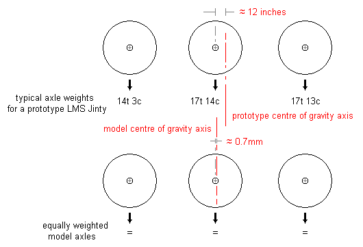
Taking an example of an LMS Jinty, the diagram adjacent shows where the prototype centre of gravity axis lies for the stated prototype axle weights, and a comparison of the model example, which shows where the centre of gravity axis needs to be if the model axles are to be equally loaded.
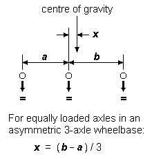 The easiest way of achieving equally loaded axles is to get the centre of gravity in its 'optimum' position. For a symmetric 3-axle wheelbase, this is directly over the middle axle. For asymmetric 3-axle wheelbases, the optimum position can be worked out quite easily from the diagram adjacent.
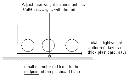 The achievement of the correct balance of a model loco fitted with a CSB (or any form of springing) is therefore important in the model design and construction process.
Weight relationships between CSB and non-CSB sprung components
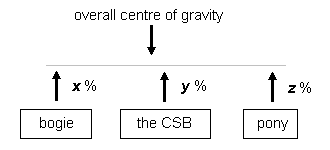
Where a loco has a CSB over some wheels but not others, e.g. a Pacific, the overall CofG of the loco will distribute the overall weight amongst the bogie, the CSB over the drivers, and the pony, all according to conventional principle of moments. Although a shift of CofG will alter the value of y (the amount of overall loco weight impinging on the CSB), it will not alter the relative distribution of y through the CSB itself to the drivers, which will remain as set by its fulcrum point positions.
Model bogies and ponies do not need to support the kind of equivalent weights the prototype needs to, and thus the prime function of model bogies and ponies is such that their strengths (the upward force they exert) is to keep the loco mainframe, and thus the CSB, horizontal. It is therefore desirable for a bogie or pony to have a reasonably consistent downforce over its expected vertical travel distance, to keep the drivers doing their intended work. Too much strength on the bogie and pony will lift the drivers, dramatically decreasing their tractive ability. Typically, on a prototype Pacific, the drivers will take 65% of the overall loco weight.
Should CSBs be extended to include bogies?
Extending a driver CSB to include a bogie is not recommended for a number of reasons:
- The bogie would not only need to move up and down, it would need to be able to rotate (yaw) and move laterally by a small amount, to make the chassis able to get round curves. Mechanical complexity aside, the height setting (beam axis to railhead, simplistically) would need to be engineered to a tolerance better than say 0.1mm (for 4mm scale).
- If a bogie shares the main driver CSB, a question arises as to whether it should have the same springrate as the drivers. (There is a strong argument that it should not - a rail height undulation of say 0.25mm (approx half the design deflection) over a distance of the driving wheelbase (say 60mm) is one thing, but if you are expecting a deflection to cope with a track length of 100mm, the '0.5mm' design deflection becomes more questionable. On a convex vertical curve, the bogie could simply float off into space, and on a concave one, the drivers could be left spinning.)
- If the bogie shares the main CSB, whatever value is chosen for the deflection characteristic of its span, it's nearly impossible to arrive at a sensible distribution of weight between drivers and bogie wheels, together with a sensible CofG position.
- If the bogie shares the main CSB, the proportion of weight between the bogie and the drivers cannot be altered after the design stage for a given CofG position.
- There usually isn't enough frame length in front of a bogie to put the frontmost fulcrum point.
To allow pitch freedom but be stiff enough to counteract any tendency for the loco to roll, bogies are probably best dealt with by having internal sprung compensation beams.
Intentional alteration of outer axle weights and/or deflections
For 2-4-0s (or 0-4-2s), modellers are likely to want to increase the proportion of the overall loco weight on the coupled axles. A typical desirable percentage spread for the axles of a 2-4-0 might be 30%, 35%, 35% respectively. If a CSB over the entire wheelbase is desired, it is possible to use the 3-axle spreadsheet for this purpose: for a 2-4-0, this can achieved either by extending the front fulcrum point forward (thereby increasing the deflection of the front axle), or by reducing the front axle load and rejigging the fulcrum points to keep the deflection the same as the other axles. The CofG will need to be positioned with care if porpoising is to be avoided and the coupled axle loads are to remain reasonably equal.
Horizontal forces on the beam
As already stated, a CSB of the type described on this page is not intentionally constrained along its longitudinal axis by any additional longitudinal force, and, in operation, the beam will rotate around each fulcrum point and will move along the fulcrum point to a small degree. This movement is subject to the friction between the beam and the fulcrum points. Because the whole of the sprung weight of the loco bears on the fulcrum points, the magnitude of this undesirable frictional force, which is proportional to the vertical reaction force at each fulcrum, can be considerable. For a loco of weight W, the magnitude of the sum of the horizontal frictional forces will be between 0.05W and 0.5W, depending on the presence or absence of lubrication at the fulcrum points. Depending on how the beam is tensioning or relaxing, the directions of adjacent frictional forces are rarely the same however, so their effect is reasonably symmetrical over the wheelbase, although the maximum values of these frictional forces will be concentrated toward the middle of the frame, as this is where the frame reaction forces are the highest. These undesirable frictional forces can be minimised by keeping the fulcrum points lightly oiled.
In addition to the horizontal frictional forces on the beam, the movement of the beam is also subject to the vertical frictional forces between the hornblocks and their guides.
Notes on frequency response
Most of our 4mm scale loco springs have a springrate k in the region of 0.7N/mm. The natural resonant frequency f of such an individual spring is therefore in the region of 20Hz to 25Hz:
f = (k ∕ m)0.5 ∕ 2π
The only source of excitation that could approach such a frequency is the wheels. A single eccentric wheel, of say 12mm diameter, could begin to drive its beam into harmonic oscillation at around the 125smph region – however, because the beam is continuous and each axle span is in series with the adjacent axle span, the harmonic oscillation could be produced only if accompanied by an adjacent wheel on the chassis working at or near a maximum phase angle of 90° in relation to the first wheel. Taking the loco as a whole though, its effective springrate is the sum of the individual springrates (the springs being in parallel, as far as gravity is concerned), so the effective overall frequency will be four times the springrate of an individual span in the case of a 4-wheeled loco, and six times in the case of a 6-wheeled loco, etc. A single eccentric wheel will be damped by the rest of the system, and it is unlikely that a number of eccentric wheels will be or remain at the same excitation phase angle in the resonance region. There could be a problem if all the wheels were eccentric, and were synchronised near the maximum excitation phase angle, and the vehicle was travelling well in excess of 200smph. The likelihood of this combination of circumstances is negligible. Lesser speeds are below resonance, and beam deflections will always be in phase with eccentric wheels and track undulations.
The presence of friction at the axle and fulcrum points of the beam, and between the hornblocks and their guides, gives a substantial degree of damping to the beam response, and it is probable that the damping ratio ζ will be in the region of 1.
A note on frame reaction forces
 The chassis fulcrum points take the sprung weight, i.e. the weight of the loco body and the weight of the sprung part of the chassis. In the case of a chassis without uncoupled wheels for example, the chassis takes all the sprung weight. This weight is not equally proportioned between the chassis fulcrum points.
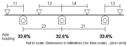
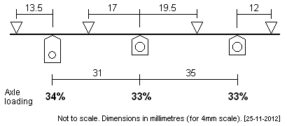
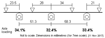
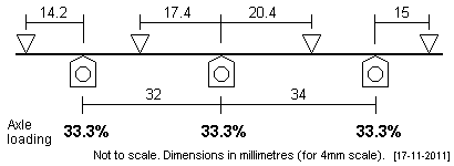
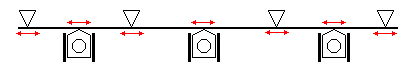
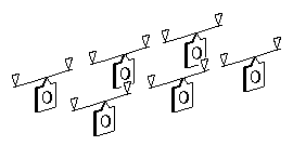
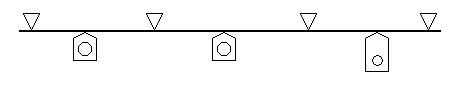
The diagram adjacent shows examples of the static loads for 2-axle, 3-axle and 4-axle cases. The sum of the frame reaction loads equals the sum of the wheel reaction loads, in accordance with the principle of moments. The percentage forces are expressed per side. The diagrams assume a centre of gravity in the middle of the wheelbase, and a theoretically rigid chassis frame. In practice, a chassis frame will not be absolutely rigid.
The unequal magnitudes of these frame reaction forces need not concern us.
Effect of fulcrum widths
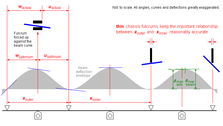
The calculated fulcrum point positions assume a zero fulcrum length. In practice, our fulcrums have a finite length, and it is not always possible to identify the precise longitudinal position where a fulcrum intersects the beam curve. Although our deflection curves are shallow, the angle at which a fulcrum intersects the beam is not always at an exact right angle. This is especially the case in outermost fulcrum points, because there is no counteracting adjacent bending moment present. Inner axle fulcrums, however, even for mildy-asymmetrical wheelbases, will usually intersect very near to the maximum peak height of the beam deflection curve. Nevertheless, the finite length of fulcrums presents a potential source of error in the intended static axle loadings.
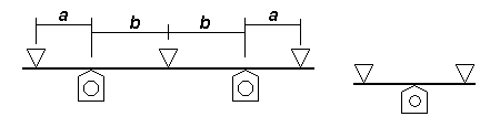
In determining the position of the outermost fulcrum points, there is therefore a compromise between:
- maximising the distance w between an outermost fulcrum and an outer axle (which will minimise the effect of the finite fulcrum length); and
- positioning the point at which the axle intersects its beam at the highest point of the deflection curve, which will ensure the fulcrum is at a right-angle to the beam curve.
If an outer axle is positioned to intersect at the maximum peak of its deflection curve, the distance w will probably be lower than we might like. If w is increased, the w and u position errors within a span decrease considerably. The compromise setting is illustrated in the final plot given in the section on Effect of moving fulcrum points on springrate.
For axle fulcrum points, the effect of their finite length on the 'within-span' w and u errors is likely to be small. The critical longitudinal objective is to keep the relationship of the inner span length to outer span length, as this is the prime determinant of the apportioning of the static axle loadings, and in this respect, narrow frame fulcrum points are desirable.
Example of axle loading differentials in an 8-coupled chassis
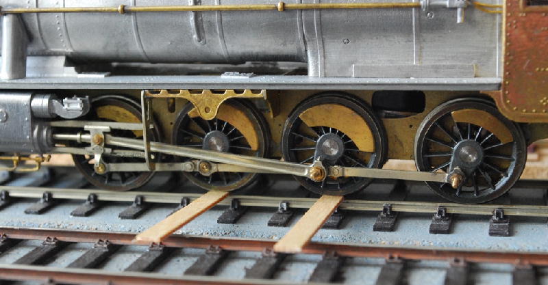 photo courtesy Dave Franks The middle axles of Dave Franks' 8F accomodating a simulated acute hump in the track. This is equivalent to a vertical curve radius of approximately 550mm, 25 times sharper than the minimum allowed (1000m) on light-railway/metro prototypes.
|
|
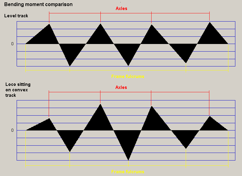
In a CSB loco, the axle loadings, chosen to be nominally equal in the static level-track case, change when the wheels encounter bumps or dips in the track. The extent of these loading changes varies according to the beam diameter chosen and by how much the track diverges from the nominally level state. The Word document produced by Roger Wyatt analyses the situation in an example 8-coupled chassis for a 0.5mm vertical track variation.
When a loco encounters a hump or dip in the track, the bending moments change. In comparing the convex track case (as in the 8F picture above) to the level track case, the greatest change in these bending moments is on all four axles and the mid frame fulcrum.
Options for 0-4-2s and 2-4-0s
There are several options for springing 0-4-2s and 2-4-0s:
- individual (non-CSB) springs:
- CSB (symmetrical) over the two driven axles, plus individual spring over the non-driven axle:
- springy equaliser over the two driven axles, plus individual spring over the non-driven axle:
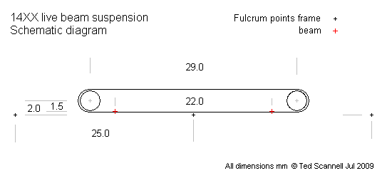
- rigid 'live beam' attached to a CSB over the two driven axles, plus individual spring over the non-driven axle (see here for application);
- CSB over all three axles (a worked example is given above for a GER E4 2-4-0):
All of the above have various advantages and disadvantages. The single CSB over all three axles is fussy about CofG placement: it will require a precise setting in the differential of block-to-beam heights between the driving and non-driving wheels, and the longitudinal settings of the fulcrum points will need to pay attention to the effect of drawbar pull and the primary direction of running.
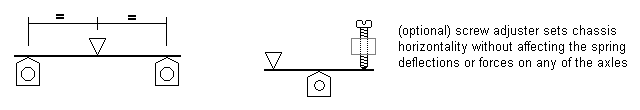
In contrast, the 'CSB over driving wheels' and the 'springy equaliser' options are not at all fussy about CofG placement, and the springy equaliser option has the advantage over the CSB case in that it makes the driver forces immune from chassis horizontality regardless of the incorporation of the optional screw adjuster. For the springrates in these two options, the non-driving axle is probably best given a smaller deflection, as this will provide good roll stability to the chassis as a whole, and this will enable a larger deflection to be used for the driving axles, which will provide a more consistent force on those wheels when traversing undulating track.
For implementation, the springy equaliser can be treated exactly the same as the equivalent in a bogie, or the springs could be trapped between the tops of the blocks and simple frame spigots.
to be continued
© Russ Elliott
first issued April 2002
symmetrical 3-axle worked example added July 2003
8F and Pannier examples added November 2003
symmetrical 2-axle case added January 2007
V1/V3 plot added July 2007
Midland standard plot added December 2007
Section on effect of moving fulcrum points on springrate plus another general symmetrical 3-axle case, plus explanation of load distribution to deflection relationship, added March 2008
Hudswell Clarke plot added April 2008
LRM CSB instruction sheet reference added 1 June 2008
Third symmetrical 3-axle case added 6 June 2008
Black 5 plots added 22 June 2008
Continental 0-6-0 plot added 10 September 2008
Adrian Cherry's RMweb 7mm Jinty build reference added 11 October 2008
Reference note to vertical positioning page added 16 October 2008
9F and WD 2-10-0 plots, and Collett standard plot, added 22 October 2008
Extra configurations for 10-coupled locos added 1 December 2008
Ivatt 2MT plot added 8 Febuary 2009
Section for 'CSBs without outer fulcrums' started 12 February 2009
LSWR G6 plot added 31 May 2009
Class 59 plot added 12 June 2009
'CSBs inside the total wheelbase' section added 8 July 2009
Typo amended 17 July 2009
Introduction expanded, and spreadsheet method clarified, 29 July 2009
Pannier variation added 31 July 2009
J72 and 56xx plots added 5 August 2009
N7 plot added 16 October 2009
J15 plot added 31 December 2009
45xx plot added 20 June 2010
sections on vertical adjustability and horizontal forces on the beam added 20 July 2010
Bill Bedford bearing drawing corrected 14 August 2010
High Level Models CSB jig news added 26 August 2010
Middle span to outer span ratios for symmetrical wheelbases added 2 September 2010
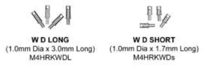
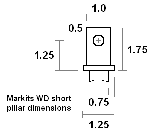
Markits WD knobs notified 5 September 2010
LNER A1/A2/A4 tender plot added 27 September 2010
Another plot for the Pannier (and Dean/Collett goods) added 30 September 2010
S&DJR 7F plot added 24 October 2010
Sections on frame reaction forces and centre of gravity placement added 3 November 2010
Section on intentional alteration of outer axle weights and deflections added 4 November 2010
SE&CR P plot plus additional symmetrical 3-axle case plot added 22 December 2010
High Level CSB instructions pdf updated February 2011
Standard Class 5 plot added 27 February 2011
Drummond F13 Paddlebox plot, plus section on effect of fulcrum widths, added 27 October 2011
Relationship of middle axle deflection differential to load differential revised 2 November 2011
Updated section with new spreadsheet tools added 2 November 2011
Notes on friction expanded and frequency response added 8 November 2011
Section on example of axle loading differentials in an 8-coupled chassis added 13 November 2011
Rear axle of N7 plot tightened up slightly, 17 November 2011
Extra plot for Jinty added 17 November 2011
Loading percentage values introduced instead of emphasising deflection differentials, 18 November 2011
Section on equitable loading of axles added 21 November 2011
RMweb references deleted because all the links have changed and cannot be searched anymore, 19 December 2011
Plot for LMS jackshaft shunter added 30 December 2011
Plot for LNWR G1/G2 added 15 September 2012
Plot for GER E4 2-4-0 added 23 Febuary 2013
Section on Options for 0-4-2s and 2-4-0s added 26 February 2013
Caveat on method for deriving plots for 'CSBs inside the total wheelbase' added 23 May 2013
Roger Wyatt's spreadsheet now shows CofG location, 2 July 2013
Introduction expanded slightly, 23 September 2013
LNER 4200g group standard tender and CR Class 782 added 13 January 2014
LNER J67/J68/J69 plot added 18 February 2014
Will Litchfield's spreadsheet now v4.2, added 11 March 2014
Reference to CSB Source Book added 16 March 2014
Section on taking into account unsprung mass added 10 April 2014
Section on Weight relationships between CSB and non-CSB sprung components added 17 April 2014
GWR 42/72xx plot added 20 May 2014
North London 0-6-0T added 2 June 2014
Section on Should CSBs be extended to include bogies? added 16 June 2014
Plots for WD 2-8-0 and Hawthorn Leslie 5'6"+5' added 23 January 2015
Plot for GWR 28xx added 25 March 2015
Alan Turner's spreadsheet updated 2 September 2016
Plots for SECR R1, GER J69 and J65 added, 6 September 2016
Plot for CR 812 class added 14 January 2017
Plot for Collett Goods added 4 February 2017
'live beam' sketch added 25 April 2017
Plot for North London Park tankd added 30 May 2017
Plot for Midland 1F added 4 December 2017
Plot for LNER J77 added 3 December 2018
plot for LNER J94 added 30 January 2019
plot for Kitson Consett A class added 16 December 2019
plot for L&Y Class 23 saddle tank added 18 January 2020
8F plots re-expressed to nearest 0.5mm increments 29 January 2021
| Return to top of page | Beam menu page | Safety, privacy and cookies |