Suggestions for the setting out of the vertical position of the fixed fulcrums on a CSB chassis
by Ted Scannell
This setting out needs to be done while the frames are still in the flat. Once drawn, preferably on the inside of the frame, bolt or solder the two sides together, outside to outside, so that any cutting or drilling done is exactly the same for both frames.
There is a line a which is drawn through the static axle centres. Most kits still have these hornguide panels in place, making it a bit easier to get the line on the centreline of the axle holes. Draw this line very carefully, making sure that it is straight and level with the tops or bottoms of the holes, as this is the datum line from which all subsequent lines are measured. If you mess this one up, just start again on the other frame side.
When the loco is sitting stationary on the track, the beam will be bent upwards at the axleboxes. This is called the 'static deflection'. In motion, this distance will vary, both up and down, according to the forces acting on that particular wheel.
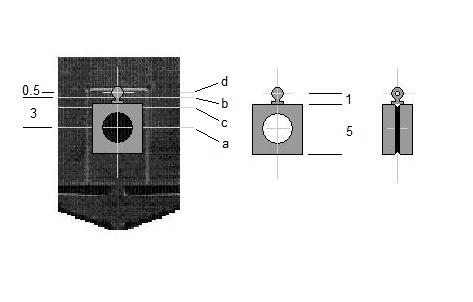
Shown on the diagram is the example of a standard Alan Gibson bearing block with a Markits 'original' handrail knob (Markits reference M4HRK 1.5) fitted to the top centre. The bearing is 5mm square, and the distance from the bottom of the flange on the knob to the centre of its hole is 1mm. This type of Markits handrail knob is recommended because it is stronger than scale handrail knobs. With the components shown, the distance between the axle centre line and the handrail knob hole centreline is (5 ∕ 2) + 1, i.e. 3.5mm. So in this example, the distance between line a and line b on the frames would be 3.5mm minus the static deflection, i.e. 3.0mm. Note: If the wire is used under the bearing block, as may be desirable in some chassis types, the static deflection must be added to the a – b dimension, which in this case would become 4.0mm.
|
Chris Pendlenton defined the optimum value of this static deflection at 0.5mm, or 1.5 scale inches, in his Hal o' the Wynd article in MRJs 28/29/30, and there has been no reason to redefine since.
The line d in the diagram represents the position of the centre of the hole in the handrail knob in this deflected condition. The holes for the frame fulcrums must be below this line. Line d should be virtual only; it won't help to draw this one on the frames.
Line b is the one on which the centres of the holes in the frame knobs, if that is what you are using, should be set. If using the LRM fixed fulcrum etches, the slots should be on this line.
Assuming the dimensions given, line b should be drawn, I suggest with the point of a scalpel blade, exactly 3mm above and parallel with line a. For different size bearings, or different height handrail knobs or other fulcrum hardware, this dimension must be adjusted accordingly.
It is along this line b only that the frame handrail knob holes are drilled (or fixed fulcrum etches attached), according to the longitudinal position plot to which you are working.
Line c represents the fouling limit, above which nothing should interfere with the movement of the wire and bearing block. The wire and bearing must be allowed to move freely downwards as well as upwards, 0.5mm above and 1.0mm below the static deflected position, to cater for the response to changing dynamic loads. Line c can be drawn in as a datum line, down to which any horncheeks or adjacent bulkheads need to be cut or filed to ensure full free movement of the wire.
Adjustment, wire diameters and fulcrum considerations A fundamental part of the CSB system is that, provided the setting out is done carefully and accurately, and the axle hole centres were in the correct place initially, no adjustment is necessary. Some correction of the static deflection position may be required according to the final weight of the vehicle, and this is done either by adjusting the weight or by changing the wire diameter, or both, in order to achieve the correct ride height. This does assume however, that the centre of mass of the vehicle is somewhere near the centre of the sprung wheelbase. If this is not the case and cannot be corrected without a drastic rebuild, and this imbalance can be predicted, shortening the span(s) at the heavy end will help. Alternatively vertical adjusters could be included, either a screw version, or a plate with a selection of fulcrum holes as on the LRM etch, but these are individual choices and outside the scope of this description.
The correct wire diameter will vary according to the weight of the vehicle and the length of the spans between fixed fulcrums. In practice, for locomotives and tenders, this most commonly falls in the range 0.013" to 0.016". (For the fully metricated, these diameters are given in thousandths of an inch because the most conveniently available source of spring steel wire, guitar strings, are described in this way. To convert, 0.1mm = 0.00394", or near enough 0.004".)
Some prototypes, 4-coupleds in particular, allow for longer fixed fulcrum spans, and thicker wires may be required, but rarely up to the maximum 0.024" found in guitar strings.
It is good practice, where there is a choice, to go for the longest possible span(s) and thicker wire to achieve the desired static deflection for a given weight.
During the development of the CSB concept, the convenience of using the Markits handrail knobs for both fixed and moving fulcrum points was simply too great to ignore. Kit and component manufacturers who include CSBs as an option, quite rightly are developing other, more convenient methods. For the basic conversion or scratchbuild, these knobs are still a very useful item. The holes in them are 0.6mm (0.024") diameter.
The vertical calculations above use the hole centres as the datums. To be strictly accurate, this generates a ride height error of a magnitude depending on the difference between the wire diameter used and the hole in the knob. Within each fulcrum point the error is half of the difference between the diameter of the wire, and that of the hole, so using 0.014" wire in 0.024" holes gives 0.005". Since the fixed and moving fulcrums work in opposite directions, the errors are summed, so in this case the total error is 0.010" ( 0.25mm), or a scale 3/4", and the vehicle will sit that much low. Since the fulcrum points are generally fixed before the wire diameter is decided, adjusting the a – b distance to take account of this is something of a lottery, so whether or not to do this is to each modeller's personal preference.
The fulcrum points do not have to be holes, they could be hooks or open cradles, provided the wire is always guided to seat properly in the right place. An advantage of holes is that the wires will then prevent the wheelsets dropping out, and no other constraint is needed to retain them. To release them the wires are simply withdrawn. Another advantage of holes, especially in the moving fulcrums above (or below) the axles is that they hold the bearings transversely on the axle. If this feature is used, it will then be necessary to control the sideplay of the axle with a washer or spacer between the back of the wheel and the frame, as the hornguide is no longer required. If preferred, the hornguide may still be retained to perform its traditional function.
Note on longitudinal restraint The CSB should not be constrained longitudinally by anything attached to the fulcrum points, fixed or moving. There is usually a handy bulkhead in the chassis for the ends of the CSB to bump into, round which they can be sprung for easy removal/replacement. Sometimes this is a bufferbeam. Or a standout plate can be soldered to the inside of the chassis so that it just gets in the way.
If this is still not convenient, one end of the wire can be bent to 90 degrees, and passed through a suitably oversize hole, say 1.5mm, so that the wire can still move freely, in any handy piece of platework. An example of this method can be clearly seen on the fourth picture down on here.
A further, desperation tactic, would be to slide a constraining collar to the ends of the wire, a crimp as is used with memory wires, or a piece of very small bore silicone tube, provided that doesn't touch the frame and inhibit the wire's movement.
© Ted Scannell
16 October 2008
| Return to top of page | Beam menu page | Safety, privacy and cookies |