.gif) |
|
| this page hosted by | |
Scalefour Digest 41.0
Issue 2, December 2003
The principles of model locomotive suspension
by Russ Elliott
Contents
Acknowledgements
1 Scope
2 Introduction
3 Problems encountered with rigid chassis
4 Advantages of suspension
5 Requirements for model locos
6 Note on terminology
7 Characteristics of rigid beam suspension
7.1 Three-point suspension
7.2 Force exerted at railhead in rigid-beam suspension
7.3 Degree of stability in three-point suspension
8 Characteristics of spring suspension
8.1 Principle of a spring
8.2 Viability of springs in small-scale models
8.3 Spring-assisted hornblocks
8.4 Suspension points
8.5 Spring beam configurations
8.6 Deflection of a spring beam
9 Principles of weight distribution
9.1 Transverse weight distribution
9.2 Longitudinal weight distribution
9.3 Allowance for motor weight
10 Comparisons between beams and springs
10.1 Introduction
10.2 Springy equalising beams
10.3 Combinations of springs and beams
11 The importance of balance
11.1 Introduction
11.2 Centre of gravity, and overall weight
11.3 Haulage considerations
11.4 Effect of drawbar pull
12 Practical aspects
12.1 The fixed axle
12.2 Weighted tender
12.3 Axleboxes/hornblocks
12.4 Equalising beams
12.5 Gearboxes
12.6 Gearbox torque reaction control
12.7 Coupling rods
12.8 Split axles
13 Worked examples
14 0-4-0, 2-2-0, 0-2-2, Bo bogie
14.1 Rigid beam arrangement
14.2 Weight distribution and stability for rigid beam arrangement
14.3 Spring arrangements
14.4 Weight distribution and stability for spring arrangements
15 0-6-0, 0-4-2, 2-4-0, 2-2-2, Co bogie
15.1 Introduction
15.2 Fixed axle rigid beam configurations
15.3 Weight distribution and stability for rigid beam fixed axle configurations
15.4 Fixed axle and spring arrangements
15.5 Rigid beam configurations without a fixed axle
15.6 Springing for all axles
16 Additions to the basic coupled wheelbase: pony and radial trucks
16.1 Introduction
16.2 A variety of approaches
17 4-4-0, 0-4-4
17.1 Introduction
17.2 Fixed axle arrangement with rigid beams
17.3 Arrangements without a fixed axle
17.4 Weight distribution and stability for 4-4-0s and 0-4-4Ts
18 Additions to the basic coupled wheelbase: bogies
18.1 Introduction
18.2 Side control for bogies
19 4-6-0, 2-6-0, 4-4-2
19.1 Introduction
19.2 Fixed axle arrangements
19.3 Weight distribution with fixed axle arrangements
19.4 Use of springy equalising beams, and alternatives to the conventional fixed axle position
19.5 Springing
20 0-8-0, 2-8-0, etc.
20.1 Introduction
20.2 Rigid beam arrangements
20.3 Springs
20.4 Weight distribution and stability
21 Specific matters on drive bogies
21.1 Introduction
21.2 Use of three-point suspension
21.3 Use of four-point and multi-point suspension
Annexes
1 Glossary of terms
2 How to determine the centre of gravity axis of a prototype loco
3 The desirability of equal loading of driven axles
4 The effect of drawbar pull
5 Friction
6 The effect of curves on the centre of gravity
7 How much vertical hornblock movement is necessary?
8 Use of more than one fixed axle
9 Further reading
Figures
1 Axles require independent vertical and rotational movement in their transverse vertical planes
2 Directions and rotations: terminology
3 Basic three-point suspension principle
4 Extended three-point suspension principle
5 Inverted three-point suspension principle
6 Degree of stability in three-point suspension
7 Force v deflection for a spring
8 Spring-assisted hornblock (coil)
9 Coil spring deflection
10 Spring-assisted hornblock (leaf)
11 Springing allows multiple suspension points
12 Spring beam configurations
13 Transverse weight distribution
14 Longitudinal weight distribution
15 Principle of moments (1)
16 Principle of moments (2)
17 Weight distribution with non-continuous springs
18 Allowance for motor weight
19 Transverse body stability for rigid beam locos
20 Weighted tender
21 'Free link' tender bogie
22 Rollplane freedom for hornblocks
23 Beams on hornblocks
24 Spring beam hornblock
25 Adjustable height spring beam hornblock
26 Coil spring implementations
27 Mounting of rigid equalising beam
28 Mounting of springy equalising beams
29 Swivelling yoke beam
30 Gearbox torque reaction control: basic principle for fixed axle
31 Gearbox torque reaction control for fixed axle with separate gearbox
32 Gearbox torque reaction control: basic principle for non-fixed axle
33 Gearbox torque reaction control for non-fixed axles
34 Pivoting beam for one axle of a rigid beam 0-4-0
35 Mike Sharman arrangement for rigid beam 0-4-0 ('swing axle')
36 Torsion bar unit for four-wheeled bogie
37 Weight distribution for 2-axle sprung chassis
38 Compensated 0-6-0 with fixed axle
39 Compensating action of 0-6-0
40 2-4-0 and 0-4-2: basic arrangement
41 Compensated 0-6-0: principle of weight distribution
42 Compensated 0-6-0: good stability and good weight distribution are incompatible
43 Compensated 0-4-2 and 2-4-0: both stability and coupled axle weights are compromised
44 Fixed axle and springy equalising beams 0-6-0
45 Fixed axle and individual springs arrangement
46 0-6-0: example of rigid beam suspension for all axles (not recommended)
47 0-6-0: rigid beam suspension for all axles using 'swing axle' arrangement
48 Example of improved weight distribution for 0-4-2T
49 Springing on all axles for a three-axle loco or Co bogie
50 Springing on all axles for a three-axle loco using springy equalising beams
51 Three-axle quadruple springy equalising beam arrangement
52 Suggested spring arrangement for a 2-2-2
53 Pony truck weight
54 Simple beam spring for pony truck
55 Simple coil spring for pony truck
56 Pony truck springing (for larger locos)
57 Separation of downward and centralising forces for pony or radial truck
58 Pony truck with hornblocks
59 Rubbing plate arrangement for heavy pony/radial truck
60 4-4-0 and 0-4-4: principle of fixed axle arrangement with rigid beams
61 4-4-0: Mike Sharman arrangement
62 Slotted bogie axle arrangement
63 Example of weight distribution for an 0-4-4T with fixed axle
64 4-4-0 and 0-4-4 without a fixed axle
65 4-4-0 and 0-4-4: suspension for all axles using swinging fixed axle 0-4-0 subchassis
66 Comparison of different suspension systems for the same 4-4-0 loco
67 Example of single-point suspension rigid beam bogie
68 3-point compensated bogie with central spring
69 Equalising springy beam bogie
70 Sideplay control for loco bogies
71 4-6-0: principle of fixed axle arrangement
72 2-6-0
73 Pony truck arrangement
74 Weight distribution and stability for fixed axle 4-6-0
75 4-6-0 and 2-6-0: uses of springy equalising beams
76 Springing for 4-6-0s
77 Different approaches for an 0-8-0
78 Weight and stability for an 0-8-0
79 Bogie articulation in diesels, electrics, DMUs/EMUs
80 Transverse and longitudinal stability
81 Springy equalising beams in a Bo-Bo
82 Representative examples of springy beam model bogies
83 How to determine the centre of gravity of a prototype loco
84 Drawbar couple
85 Moment balance for drawbar pull
86 Drawbar pull on drive bogie systems
87 Friction
88 Effective shift of centre of gravity on curves
Acknowledgements: The initial (1985) version of this Digest was based on articles written by K.R. (Ken) Morgan and also on information produced by Mike Sharman as a result of his pioneering work on beam compensation for model locomotives, which provided an important boost in the development of finescale modelling, and thanks are extended for allowing the continued use of relevant parts of their texts in this revision. The author would also like to thank the following, who have contributed material, inspiration, thoughts or practical experience to this revision: Gordon Ashton, Bill Bedford, Dave Bradwell, John Brighton, Chris Copplestone, Simon Dunstall, Martin Finney, Jan Frelin, Stephen Gifford, John Hayes, Dave Holt, Roger Howell, Mark Humphrys, Keith Norgrove, Andrew Nummelin, Chris Pendlenton, Andy Reichert, Iain Rice, Pete Runnacles, Ted Scannell, Ian Strange, Richard Tearle, Roger Wyatt.
1 Scope
This section of the Scalefour Digest describes the principles of suspension for small-scale model locomotives. Descriptions of constructional methods have been limited to those aspects necessary for the understanding of the principles involved.
[Contents]
2 Introduction
The term 'better running' may be looked at from several viewpoints; of these, the most important is freedom from derailment, followed closely by controllability of locomotives and their performance in terms of balance, stability and haulage capacity.
Traditional ready-to-run locos and vehicles with rigid chassis have wheels that avoid derailment only by having flanges of sufficient depth to cope with the variations to be found in model trackwork. The incorporation of nearer-to-scale flanges in rigid chassis exacerbates this situation, so the adoption of correct scale wheels requires a move away from the rigid chassis approach to a form that emulates the flexibility and performance of a prototype chassis.
There are relatively simple solutions to the problem of trackholding, and the solutions adopted as a matter of necessity by modellers working to finescale standards will also greatly enhance the running characteristics of any small-scale model railway loco or vehicle, irrespective of the wheel and track standards used.
[Contents]
3 Problems encountered with rigid chassis
There are a number of sources of potential error inherent in a rigid chassis:
- Although tools will have been used to press or drill or mould the axle holes in commercial models, small inaccuracies will nevertheless occur, and misalignment between the holes of a few thousandths of an inch, say 0.002" to 0.003", may be found. The scratchbuilder of a rigid chassis may have access to machinery to put in his axle holes, or if he has a pillar drill and is skilled he may align the holes to within about 0.005".
- Some or all of the following defects will be present in wheels: eccentricity; ovality; diameter variation; wobble. In the best wheels these defects will be very small, but they will be there.
- Carrying wheels in rigid chassis rarely perform their correct function, namely carrying. In most cases they merely go along for the ride, sometimes being lightly sprung in order to maintain contact with the track. Modellers have to go to considerable lengths if desiring to balance such a model correctly on its coupled wheels.
Finally, there will be errors in the track on which any vehicle or loco is run, since the materials and facilities available to modellers make it impossible to build and maintain absolutely level track. Good track will get close to this ideal, but there will still be some slight bumps and hollows, while gradients and superelevation bring deliberate departures from the level datum.
Although each of the individual errors may be small, together they can add up to a considerable amount. It is not surprising then that a rigid chassis will not perform correctly in terms of trackholding, stability or haulage, since the model contacts the track with some of its wheels all of the time, all of its wheels some of the time, but never all of its wheels all of the time.
[Contents]
4 Advantages of suspension
Experience largely confirms the following advantages for vehicles and locos with proper suspension.
(a) All wheels contact the track at all times, and as a result:
- driven axles always apply traction to the rail;
- electrical contact is much improved, which assists in smoother running, cuts out any arcing at wheel treads, which helps to reduce the buildup of dirt on wheel treads, and as a side effect reduces electrical interference.
(b) Errors in commercial wheels and related components are better accommodated.
(c) All wheels are made load-carrying, which can help to alleviate the problem of 'balancing' such wheel arrangements as a 4-4-0 or 0-4-2T, where the usual placement of motors in models makes proper weight distribution difficult.
(d) The appearance of the engine in motion is much improved, as its stability and balance gives the illusion of a much larger and heavier vehicle.
[Contents]
 Figure 1 Axles require independent vertical and rotational movement in their transverse vertical planes
5 Requirements for model locos
The main requirement for good running consists in maintaining continuous and consistent contact between all wheels and the track:
- Continuous contact is achieved by allowing wheelsets to have vertical movement with respect to each other; this vertical movement is achieved by hornblocks or axleboxes (or tubular bearings) that can move up and down in the loco frames or chassis (see figure 1).
- The consistency of contact between wheels and track is achieved by making the weight of the loco bear upon the axles or group(s) of axles by means of springs or beams.
- The correct consistency of contact between wheels and track, in order to optimise the balance, stability and drawbar pull of the loco, is achieved by choosing a suitable arrangement of beams and/or springs for the particular chassis involved.
[Contents]
 Figure 2 Directions and rotations: terminology
6 Note on terminology
The meanings of the directions and the different modes of rotation, as used in this Digest, are shown in figure 2.
A glossary of some terms used in this Digest is given in annex 1.
Note: Unless otherwise specified, values shown on the figures are in millimetres.
[Contents]
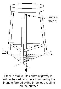 Figure 3 Basic three-point suspension principle
7 Characteristics of rigid beam suspension
7.1 Three-point suspension Rigid beams do not in themselves deflect sufficiently under load for our trackholding purposes, and we have to deploy them in a particular geometric configuration to get the required vertical axle movements. Three-point suspension is based on the fact that any object carried on three points will always maintain contact between those points and the surface on which it is placed, provided the object's centre of gravity is contained within the vertical space bounded by those three points. Everyday examples of this are tricycles and three-legged stools (see figure 3). Conversely, the weight of any object carried on more than three points will rock if placed on an uneven surface. Rigid chassis models with no suspension act as though they have a maximum of three wheels. Prototype railway vehicles transmit their weight on more than three points, since the least number of wheels encountered is four, while most locomotives have many more. Where rigid beam suspension is employed, we therefore need to persuade our model vehicles to have only three suspension points, thereby keeping all their wheels on the track.
The three-point principle holds true if one or more of the 'legs' are themselves supported by three legs (see figure 4).
Another convenient way of viewing how three-point suspension works is by inverting the stool, i.e. any body is able to rest stably on three points projecting equally (or thereabouts) from a horizontal plane (see figure 5).
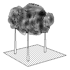 Figure 5 Inverted three-point suspension principle
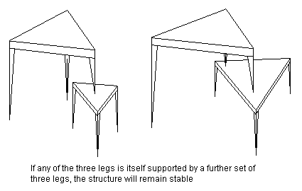 Figure 4 Extended three-point suspension principle
[Contents]
7.2 Force exerted at the railhead in rigid-beam suspension For a given centre of gravity, the proportion of the loco weight bearing onto a particular axle is constant. In a loco with rigid beam suspension, the reaction force between the wheels and the railhead will also be that same proportion of the loco weight bearing onto the axle, regardless of the state of the track. (Strictly speaking, this applies only to the static situation, but we can ignore the differences applying at the wheel/rail interface arising from the dynamic effects of undulating track on the vertical acceleration and deceleration of the wheels and the rest of the loco they support.)
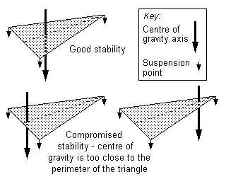 Figure 6 Degree of stability in three-point suspension
7.3 Degree of stability in three-point suspension Although the legs of a three-legged stool will rest on any surface, the degree of stability of the stool will depend on exactly where its centre of gravity is in space in relation to the position of the three legs resting on the surface. The stability of a chassis will become compromised if the loco centre of gravity gets close to a transverse vertical plane of any primary suspension point. Figure 6 illustrates this principle.
If the centre of gravity line lies outside the triangle, the chassis will be unstable.
[Contents]
8 Characteristics of spring suspension
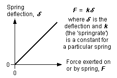 Figure 7 Force v deflection for a spring
8.1 Principle of a spring In distinction to a rigid beam, a spring, regardless of its form or shape, will exert a changing force as it deflects its hornblock. This relationship is linear, with maximum force being applied when the spring is fully compressed (to take the example of a compression spring), and zero force being applied when the spring is in its fully relaxed state – this principle is shown in figure 7. The actual deflection of the spring is directly proportional to a property, the 'springrate' (or 'spring constant') of the particular spring.
If a spring relaxes to depress a wheel onto the rail, the reduction in the force applied to the hornblock will be counterbalanced by a distributed increase in the force the loco applies to its other suspension points. Springs absorb and discharge potential energy, and decouple the vertical forces between the wheels and the body.
Thus in a sprung loco traversing uneven track, there is a continuously changing set of forces applying between the wheel tyres and the rail, although the sum of those forces at the railhead is constant.
The action of a spring in a prototype loco is related to the weight borne by the particular axle involved, and on the prototype each spring is designed to bear and operate on a specific load. If the spring is too strong, the weight of the loco will not cause it to operate properly over irregularities in the track, while if the spring is too weak the loco is likely to show dynamic instability.
8.2 Viability of springs in small-scale models A prototype loco is suspended, being held up by the strength of the springs. It is generally accepted as being difficult to reproduce the characteristics of prototype springs in small-scale models because:
- the mass to momentum relationships in the prototype do not scale linearly to models;
- with the exception of the use of commercial music wire strings as beam springs, it can be difficult to provide the range of model springs appropriate for all the different weights of model locomotives;
- it can be difficult to adjust the springs so that the loco is both level and at the correct buffer height;
- it is difficult to assess what the design value of the deflection of a spring should be;
- model rail does not deflect under the weight of a model loco like prototype rail does.
[Contents]
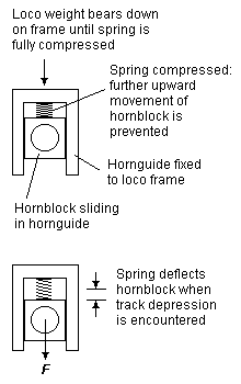 Figure 8 Spring-assisted hornblock (coil)
8.3 Spring-assisted hornblocks A spring-assisted hornblock is one traditionally containing a coil spring between a hornblock and its hornguide. Under the weight of the loco, the spring compresses either fully (to bind the coils together) or until the hornblock is restrained from further upward movement by some limiter device fitted to the hornguide or the frames of the loco – see figure 8. The spring in such a hornblock therefore depresses its axle into depressions of the track, and the deflection is in proportion to the springrate of the particular spring. The downward force of the spring will diminish the greater the depression of the track (see figure 9).
Spring-assisted hornblocks do not provide the equalising advantages of beams, nor (when in their fully compressed state) the shock-absorbing advantage of properly suspended springs – any upward projection of the track will transmit itself directly and abruptly to a loco chassis fitted with spring-assisted hornblocks. Moreover, if the spring rating is not chosen to match the weight being supported, a loco fitted with spring-assisted hornblocks may show non-optimal haulage, depending on the state of the track.
Note: The above does not imply that all coilsprung hornblocks operate in a 'spring-assisted' fashion as described above.
A cantilever leaf spring can also be used to act in a spring-assisted fashion – see figure 10.
 Figure 10 Spring-assisted hornblock (leaf)
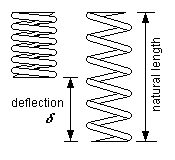 Figure 9 Coil spring deflection
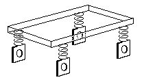
(a) Representative suspension points on an 0-4-0
|
(b) Representative suspension points of a modern prototype bogie
|
| Figure 11 Springing allows multiple suspension points | |
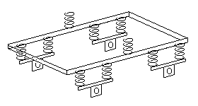
8.4 Suspension points In contrast with rigid beam suspension, there is no limit to the number of primary suspension points allowed for springs. An 0-4-0 has four suspension points (see figure 11(a)), an 0-6-0 or Co bogie has six, an 0-6-2 has eight, and so on. This principle applies to more complicated cases where more than one 'layer' of springing might be involved, and figure 11(b) gives a representation of a prototype example of an EMU/DMU having two main suspension points between each bogie and the body, and two suspension points for each wheel to the bogie frames: in such more complicated cases, the notion of what constitutes the difference between 'primary' and 'secondary' suspension points becomes somewhat academic.
[Contents]

(a) Spring beam between two simple supports
(b) Cantilever beam
(c) Multiple span ('continuous') spring beam

(d) Equalising spring beam
Figure 12 Spring beam configurations |
8.5 Spring beam configurations The deflection of a spring beam varies considerably depending on how it is supported. A common form of support, and one that lends itself to being able to control the datum height of the hornblock when under deflection, is where the hornblock spring is restrained loosely against two fulcrum points – see figure 12(a). The beam can slide along and rotate freely around these 'simple' supports, according to the force being applied to the beam.
The cantilever spring (see figure 12(b)) is one where the spring is fixed rigidly at one end only. This spring configuration is probably the most difficult to control in terms of being able to set the datum deflection height of the hornblock accurately, but has the virtue of being easily adjustable.
Multiple hornblocks can be supported by using multiple instances of figure 12(a), or by using a continuous single spring beam held against multiple fulcrum points – in figure 12(c) for example, depending on the strength of the spring beam, a significant degree of equalisation will be imposed between adjacent hornblocks.
Full equalisation is given where a single spring beam bearing onto two hornblocks is allowed to pivot about a point (typically the midpoint) along its length. See figure 12(d). The degree of equalisation given by the beam will depend on its strength; if it is too weak, it will not act sufficiently to rotate itself about the pivot, and if it is too strong, it will become in effect a rigid beam.
The behaviour of all of the above examples of spring configuration will be significantly different from each other, and slight variations in the cross-sectional area of the spring material and distances between fulcrum points will produce very different deflection values.
8.6 Deflection of a spring beam The deflection of a spring beam depends on its length, its cross-sectional shape, the material, where the deflecting force is applied, and how the beam is supported. Equations concerning such deflections are beyond the scope of this Digest sheet – see annex 9.
[Contents]
 Figure 13 Transverse weight distribution
9 Principles of weight distribution
9.1 Transverse weight distribution In model locos, we can normally assume an equal transverse weight distribution – see figure 13.
 Figure 14 Longitudinal weight distribution
 |
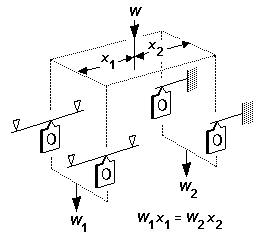
9.2 Longitudinal weight distribution Longitudinal weight distribution follows the rules of the principle of moments. The simplest example of this is shown in figure 14 for the two-axle case. The proportion of weight acting on each axle is given by its longitudinal position from the centre of gravity. The greater weight is put on the axle nearer to the centre of gravity. If for example the centre of gravity is exactly halfway between the axles, the axles will be equally weighted.
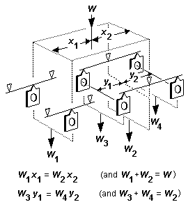
Where beams (rigid or springy) are present, weight is transferred to the wheels via the beam suspension point(s), and the proportion of loco or vehicle weight transferred at each end of a beam also follows the principle of moments. The proportion of the weight W acting at the ends of the beam in figure 15 is in proportion to the distance from the end of the beam to the point of application of weight W. The greater weight is put on the end of the beam nearer to the point of application of weight. The principle extends to any arrangement of beams, however complex (see the example of figure 16).
In practice, because of the constraints on where the actual centre of gravity of a loco will or can be, it is often difficult, and in many cases impossible, to achieve the desired longitudinal weight distribution, and therefore correct loco balance, in a chassis that uses only three-point suspension principles (see 7.3).
 Figure 15 Principle of moments (1)
 Figure 16 Principle of moments (2)
(a) Weight distribution with non-equalising spring beams
Figure 17 Weight distribution with non-continuous springs |
(b) Weight distribution with equalising spring beams
|
For sprung locos, the positions of the fixing points of the springs, whether cantilever or otherwise, can be ignored – only the axle positions are relevant. See figure 17(a). The example of a three-axle chassis in figure 17(b) shows weight imposed on the suspension points of equalising springy beams, and the further distribution of that weight along the equalising beams follows the principle of moments in the normal way.
For continuous springy beams spanning multiple fulcrum points, longitudinal weight distribution also follows the principle of moments, but the relationship between the springrate (and hence deflection under a particular force) applying to a particular axle is far more complex, and is not addressed in this Digest.
 Figure 18 Allowance for motor weight
9.3 Allowance for motor weight Where a motor drives a fixed axle, the weight of the motor is considered as part of the overall loco weight. Where a motor hangs on a non-fixed axle, a proportion of the motor weight (depending on how it is mounted in the chassis) will bear directly onto the axle, and will affect the balance of a beam distributing the loco weight between the axles. The motor weight is likely to be small compared to the overall weight of the loco, but the design position of a beam pivot point can be modified if desired to cater for the motor weight, as shown in the example of figure 18.
[Contents]
10 Comparisons between beams and springs
10.1 Introduction Rigid beams and springs both have their advantages and disadvantages.
Rigid beam chassis are generally easy to set up, with correct buffer height easily achieved for example, and such chassis are usually very good at coping with uneven track, or where the railhead divergence from the level datum is large or rapid. Traction is consistent, regardless of the state of the track. Depending on the particular deployment of the beams involved however, rigid beam chassis can be comparatively poor in terms of balance and drawbar pull, and in some cases stability can be very poor. Generally, the exclusive fitting of rigid beams becomes untenable for a chassis with a large number of wheels.
Springs are generally difficult to set up and adjust. For locos with a small number of wheels, good transverse and longitudinal dynamic stability is likely to be difficult to achieve, but in general, locos fitted with springs can have comparatively good balance and drawbar pull. Long-wheelbased locos fitted only with springs are reasonably tolerant of uneven track where the unevenness is within a short distance, but are not tolerant of track uneven over a distance of the order of the length of the loco, as in the latter case the deflection values of the springs cannot be made large enough to ensure and maintain a reasonable force exerted on every hornblock whilst also maintaining good dynamic balance.
10.2 Springy equalising beams The springy equalising beam combines the equalising advantages of a rigid equalising beam and the shock-absorbing advantages of a spring. In effect, it is simply a metallic rigid beam made thin enough in the vertical plane so that it becomes flexible.
A springy equalising beam need not be subject to the limit of 'only three points' of rigid beam three-point suspension. To take maximum advantage of this, and to bring significant benefits in achieving better transverse balance and hence improved transverse stability, the optimum use of springy equalising beams is therefore where they are mounted on both sides of the chassis. See 15.4 for example.
Ignoring dynamic effects, springy equalising beams do not give any advantage over rigid beams in respect of longitudinal stability.
Unlike rigid three-point suspension, locos fitted with springs may however exhibit a degree of roll when in motion. The extent of this roll will depend on how the wheels are driven, the accuracy of wheels and chassis components, and, where present, coupling rods and crankpins. The degree of roll can be minimised by strengthening some or all of the springs, and springy equalising beams display a greater roll stiffness compared to the use of individual coil or leaf springs. The distance between the centre of gravity of the loco above the springs will also have a marked affect on the stability of a sprung chassis.
10.3 Combinations of springs and beams The suspension of a particular locomotive may be most effectively achieved by using a combination of equalising beams (whether rigid or springy) and individual springs. The combination can under certain circumstances be applied to a group of axles; an example of this is the trailing bogie of an 0-4-4T, where a single suspension point may bear on the bogie frame, but the individual axles of that bogie could be sprung. Another example is where a single spring bears down on to a bogie, but where the axles of the bogie are themselves suspended according to the three-point principle.
The use of sprung axles for non-coupled or non-driven wheels, e.g. bogies and pony trucks, can be a pragmatic solution owing to their simpler construction compared to the incorporation of a full and possibly complex arrangement of rigid beams.
[Contents]
11 The importance of balance
11.1 Introduction Weight distribution for models is as important a consideration as it is for the prototype designer.
 Figure 19 Transverse body stability for rigid beam locos
The loco body and chassis need to be level with respect to the track. In rigid beam systems, transverse body stability is given by making two of the three primary suspension points lie in the same vertical transverse plane. See figure 19. Longitudinal stability is achieved by ensuring that the loco's centre of gravity lies within the 'triangle' of the three primary suspension points. The degree of longitudinal stability in rigid beam models is determined by where the loco centre of gravity lies with respect to the three primary chassis suspension points (see figure 6).
For sprung locos, transverse and longitudinal stability is more difficult to achieve, owing to the inherent nature of springs, but sprung locos are not limited to the 'only three suspension points' rule, and therefore rigid beam chassis that exhibit a degree of instability owing to the closeness of the centre of gravity to the three-point triangle can become more stable if any compensating beams are replaced by equivalent springy equalising beams on both sides of the chassis.
For sprung locos, the overall weight of the loco, and the distribution of that weight, are critical. These factors are not at all critical with rigid beams, as the vertical deflection of their hornblocks is neither affected by the total loco weight nor is affected by an imbalanced weight distribution.
For locos with carrying wheels, there is a trade-off, in trying to achieve a reasonable longitudinal balance, between maximising weight on the driven wheels (and thereby maximising drawbar pull) and ensuring sufficient force on the carrying wheels.
Secondary suspension points do not need to be contained within the triangle of the three primary suspension points – see figure 41, for example.
11.2 Centre of gravity, and overall weight Reference is made throughout this article on the effect and the importance of the location of the centre of gravity of the loco, and of the overall weight of the loco if using springs. In modelling, unless converting an rtr or existing loco, neither of these attributes is usually known until the loco is largely completed, by which stage critical constructional decisions will have been made as to which suspension method is most appropriate for the specific loco in question. It is strongly recommended therefore that an assessment be made at and throughout the constructional stages on the following questions:
- Is the approximate location of the centre of gravity known?
- How easy will it be to add/remove weight to alter the position of the centre of gravity if necessary?
- What effect(s) will any alteration of the centre of gravity have on balance and stability?
- Can weight be added to the loco without affecting the centre of gravity?
Annex 2 shows how to determine the centre of gravity of a loco from the prototype axle weights and wheelbase dimensions. It may be necessary to make a deliberate decision to alter the centre of gravity of the model compared to the prototype position because of the particular type of model suspension system used. There may also be model constructional aspects (motor position, for example) that will constrain where the model centre of gravity can be.
11.3 Haulage considerations Although maximum haulage is independent of load distribution amongst the driven axles, maximum stable haulage is achieved with an equal weight distribution over the driven wheels (see annex 3). In a real model loco, obtaining equal static weights for all driven axles can be difficult or impossible, but getting them to within 20% of each other would be a good result.
11.4 Effect of drawbar pull Most model locos, if suspended properly, will be able to pull typically 20% to 30% of their weight. The force (drag) of a train attached to a loco drawbar produces a couple force on the loco, and will have the effect of shifting the loco centre of gravity slightly, with the result that some of the loco wheels will produce less force on the railhead and some wheels will produce more. Prototype designers took this in account in setting out the weight distribution and wheelbase spacings.
Annex 4 describes the effect of drawbar pull, gives methods to determine how a particular drawbar pull will affect a loco, and also how to counter the effect if desired.
On a sprung loco, the couple force on the loco produced by the drawbar pull can, depending on the strength of the springs, have the effect of making one end of the loco dip slightly.
[Contents]
12 Practical aspects
12.1 The fixed axle Although engines can be built with suspension for all axles, for engines without carrying wheels, or with carrying wheels at one end only, one of the driven axles can be in bearings that are fixed in the chassis. Although such a fixed axle need not be the one where the motor transmission is taken to a group of coupled axles, it is common for this to be the case, as it conveniently allows the gearbox (and also the motor) to be fixed in the chassis, and is thus particularly useful where an rtr or rigid-chassis model is being converted.
The fixed axle must be at one end of the group of driven axles.
For engines with carrying wheels at both ends, such as 4-6-2s, or 'balanced' types such as 2-6-2s, the balancing problem is not so acute, and these engines can, for practical purposes, be treated as 4-6-0s and 0-6-0s respectively, thus 'qualifying' for a fixed axle.
For steam non-tender locos, the fixed axle is usually placed at the rear (firebox) end of the loco, since the ashpan and firebox provide convenient hiding places for gears and motors respectively. The placing of a fixed axle at the rear is (normally) highly desirable if using the weighted tender arrangement (see 12.2).
For locos exclusively using rigid beams, and therefore subject to the 'three-point rule', a fixed axle will always be the location of two of the three primary suspension points; this has significant implications on the balance and stability of locos, and will be explored later in the examples of specific wheelbase configurations.
 Figure 20 Weighted tender
12.2 Weighted tender Some loco wheel arrangements, e.g. the 4-4-0 and 2-4-0, are difficult to balance correctly, particularly if the motor is mounted within the loco firebox area. In such cases, in order to concentrate a reasonable amount of available loco weight onto the driven axles, we can consider making some of the tender weight bear onto the rear of the loco in order to achieve good traction on the driven axles. Allowing the tender to rest onto the rear of the loco will counterbalance the weight at the front end of the loco. See figure 20. It is important that the amount of tender weight allowed to rest on the rear of the loco is such as to not move the effective centre of gravity of the loco too far towards the rear of the loco, and accordingly, it is recommended that if a weighted tender arrangement is used, any fixed coupled axle in a loco fitted with a single compensating beam should be at the rear end of the loco.
An advantage of the weighted tender arrangement are closer coupling of loco and tender while being able to cope with curves, since both engine and tender now act an articulated unit.
 Figure 21 'Free link' tender bogie
If using the weighted tender arrangement, and where the rear axle of the tender is fixed relative to the tender body, the weight of the tender should bear only on a single point at the rear of the loco. The method of attachment should allow the tender to twist slightly in relation to the loco, to overcome any track irregularities present between a fixed axle of the loco and the fixed axle of the tender. The front two axles of the tender can be lightly sprung or have their beams loosely mounted from a point towards the rear of the tender (see figure 21).
[Contents]
12.3 Axleboxes/hornblocks As well as being allowed to slide vertically in their frames/hornguides, axleboxes or hornblocks should be allowed a slight degree of roll freedom – see figure 22.
Where beams are being placed on either side of the chassis frame, they need not bear onto the axles themselves, but can be arranged to lie on top of the hornblock – see figure 23.

Note: The diagram greatly exaggerates the amount of roll freedom required. Figure 22 Rollplane freedom for hornblocks |
 Figure 23 Beams on hornblocks
 |

Note: The hornblock can be below the spring (as shown) or above the spring.
Figure 24 Spring beam hornblock |
 Figure 25 Adjustable height spring beam hornblock
|
For a hornblock on a spring beam, figure 24 shows how handrail knobs can be used as the fulcrum points of the beam and as a means of holding the hornblock on the beam. The beam should be a loose fit in all the handrail knobs, so that it can bend freely. The beam can be changed easily to one of a greater or lesser strength. Figure 25 is a more elaborate variation, with an adjustable grubscrew to set the precise height of the hornblock.
Ideally, the axis of the spring should align with the centre of the hornblock, so as to prevent asymmetric loading of the hornblock.
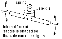
Examples of coil spring implementations are shown in figure 26.
(a) Spring axle 'saddle'
|
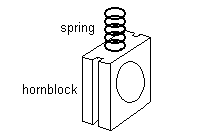
(b) Coil spring hornblock
| |
| Figure 26 Coil spring implementations | ||
12.4 Equalising beams An equalising beam should be allowed to pitch freely about its rotation point. Figure 27 shows examples of how a rigid equalising beam can be implemented, and figures 28(a) and 28(b) show how springy equalising beams can be implemented.
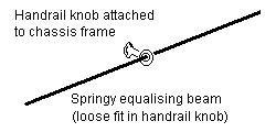
(a) Handrail knob method
Figure 28 Mounting of springy equalising beams |
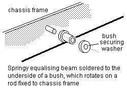
(b) Rotating bush method |
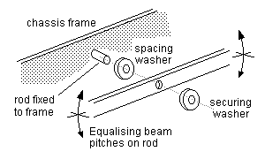 Figure 27 Mounting of rigid equalising beam
|
12.5 Gearboxes Any driven axle not fixed in the chassis frames will require a gearbox of some sort to keep the gears correctly in mesh.
Any gearbox will need to be given the same degree and freedom of movement as the axle it is mounted on. Where more than one axle is fitted with a gearbox or geartrain (as in the case of many diesel or electric locos), any transmission-connecting pieces between the gearboxes or geartrains have to allow the axles involved to continue to be able to move independently of each other in the chassis or bogie.
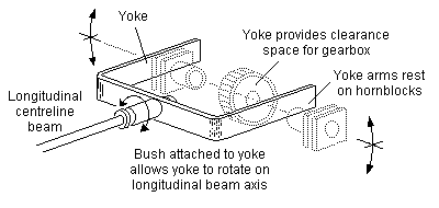 Figure 29 Swivelling yoke beam
Where a gearbox is required on an axle on which a single longitudinal centreline beam bears, it may be possible to arrange the beam to lie on part of the frame of the gearbox. If this is not possible, the end of the beam can be arranged to have a swivelling forked yoke, the ends of which bear on the axleboxes on each side of the frame, as in the example of figure 29. This arrangement has the same effect as a beam bearing on the middle of an axle, and therefore does not alter either the longitudinal or transverse weight distributions.
If a gearbox is fixed to the motor, allowance must also be made for the motor to follow any vertical (and sideways, if the wheelset is required to provide sideplay in the chassis) movement of the driven axle.
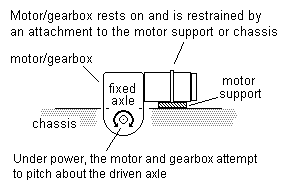 Figure 30 Gearbox torque reaction control: basic principle for fixed axle
|
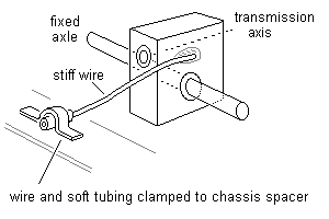 Figure 31 Gearbox torque reaction control for fixed axle with separate gearbox
|
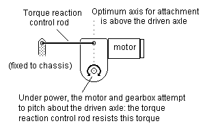 Figure 32 Gearbox torque reaction control: basic principle for non-fixed axle
|
12.6 Gearbox torque reaction control Any gearbox, whether on a fixed axle or a floating (non-fixed) one, will require the fitting of torque reaction control between the gearbox and the chassis, to counter the rotational resistance of the axle being driven. Figure 30 shows the basic principle for a fixed axle, with the motor resting on a firm or resilient support: the torque reaction is small, so the motor can be restrained from counter-clockwise movement by a loop of wire or thread. Figure 31 shows an equivalent arrangement for a fixed axle where the gearbox is not attached to the motor.
For a gearbox on a non-fixed axle, any torque reaction control must allow the gearbox and its axle to move up and down freely, and to allow it to swing in the roll plane. These requirements are simply and best met by connecting the gearbox to the chassis (or bogie frame) by a link which should be substantially horizontal along the axis of the chassis or bogie. In practice, some deviation from the horizontal will not matter, since the up and down movement required of the gearbox/axle is relatively small. A degree of slack/slop in the linkage pivots at both ends is desirable to enable the gearbox to swing. The torque reaction control link must be rigid, but can be a relatively thin piece of wire. Figure 32 shows how a torque reaction control link is fitted to a motor/gearbox combination to prevent it rotating around the driven axle, and figure 33 shows the arrangement for a separate gearbox.
Where a chassis or bogie contains more than one gearbox:
- each gearbox will require its own torque reaction control link; or
- provided that all the torque reaction control links are free to pivot at both ends, the gearboxes can be linked to each other, as long as one of them is linked to the chassis or bogie as described.
Note: A worm gearbox will try to rotate around the transmission axis, but there is no point in controlling this roll torque vector, as we want a degree of axle swing, and in anycase the value of this torque is comparatively small.
 Figure 33 Gearbox torque reaction control for non-fixed axles
12.7 Coupling rods Locos with more than four coupled wheels will require the use of jointed coupling rods for the wheel suspension action to take place. The jointing of the coupling rods should occur at, or adjacent to, the crankpin of the wheel(s) involved.
12.8 Split axles As will be seen from the diagrams, some of the suspension beams bear on the middle of the axle. To prevent shorting in such cases, either:
- the beams must be made of insulating material; or
- a 'three-part' split axle, with an insulated middle section, must be used.
Where metal beams are arranged on both sides of the axle (e.g. see 17.3), either a two- or three-part split axle can be used, but both types will present formidable insulation problems unless the frames are insulated from each other or unless the hornblocks are insulated from the frames.
[Contents]
13 Worked examples
Railway modellers are a singularly inventive bunch, and no one person can have a monopoly of the answers to every chassis problem encountered, and an article such as this should therefore be regarded as a basis on which to work, and not necessarily followed slavishly word for word. It is not possible to cover every possible variation of suspension arrangements for every possible wheel arrangement, but it is hoped that the following sections, which contain examples of both good and less good practice, will provide enough material on which sensible judgements can be made and sensible solutions achieved.

(a) Support bar fixed to frames
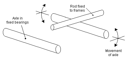
(b) Axle bears up against simple rod
Figure 34 Pivoting beam for one axle of a rigid beam 0-4-0 |
14 0-4-0, 2-2-0, 0-2-2, Bo bogie
14.1 Rigid beam arrangement For four-wheeled locos or bogies, either axle can be fixed; thus to take an unusual case of an 0-2-2 the leading axle would be in fixed bearings since it is the only possible driving axle, while the rear axle is carried in hornblocks that are allowed a small amount of vertical movement from the axle datum centreline. Figure 34(a) shows how a cross member can be arranged with a central pivot point to both control height and allow pivoting, and figure 34(b) shows a common equivalent solution using a simple rod. This principle is essentially the same method as that used on a compensated four-wheeled wagon using a rocking W-iron.
 Figure 35 Mike Sharman arrangement for rigid beam 0-4-0 ('swing axle')
Figure 35 shows an equivalent 'swing axle' arrangement recommended by Mike Sharman. Two trunnions between the frames carry a longitudinal pivoting rod, to which is soldered a tube in which the axle is placed. Coupling rods, if present, hold the wheelbase, and washers are fixed to the pivoting rod to restrict end play. In this arrangement, the axle tube takes the place of proper hornblocks (which are therefore not required) and only small slots are provided in the frames, with just enough clearance to allow the axle tube to swing without binding.
14.2 Weight distribution and stability for rigid beam arrangement Care should be taken that the centre of gravity of the loco lies within the 'stable' area of the three-point triangle of figure 6. The weight diagram is figure 14. If the loco's centre of gravity is located midway between the axles, both will be weighted equally, which is a desirable quality for an 0-4-0, but such a placement will promote a degree of transverse instability. In practice, the degree of transverse instability in an 0-4-0 is slight.
For a 2-2-0 or 0-2-2, the loco centre of gravity should be placed to favour the fixed driven axle.
For a Bo bogie, the question of transverse stability can be assessed only when it is considered in the context with the other bogie truck of the complete chassis, e.g. a Bo-Bo is treated equivalently to an 0-4-4 or 4-4-0 or 0-8-0.
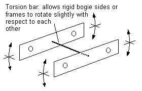 Figure 36 Torsion bar unit for four-wheeled bogie
14.3 Spring arrangements Springing an 0-4-0, 2-2-0 or 0-2-2 or Bo bogie can be achieved by fitting springs of the types shown in figures 12(a), 12(b) or 12(c).
A Bo bogie, since it will always be used in conjunction with another bogie in a complete chassis, could have its axles suspended by springy equalising beams of the kind shown in figure 12(d) on both sides of the chassis. A variation of this equalising theme is the torsion bar unit, where both sideframes are rigid, but are attached to each other by a single piece of wire that allows the frames to twist slightly with respect to each other – see figure 36. Torsion bar units are usually associated with unpowered bogies.
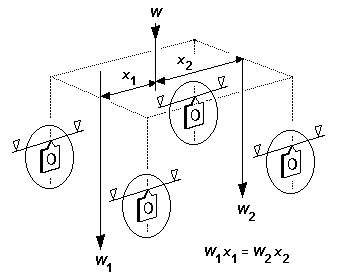 Figure 37 Weight distribution for 2-axle sprung chassis
14.4 Weight distribution and stability for spring arrangements The relevant weight diagram is given in figure 37 (which is also applicable for cantilever springs): note that, for a given location of imposed weight, the longitudinal weight distribution for springs is exactly the same as it is for a rigid beam implementation.
Transverse static stability is optimised because of the use of springs on both sides of the chassis.
Longitudinal and transverse dynamic stability however for a 4-coupled chassis are not good, and the former will depend on the state of the track, the smoothness of the loco transmission, and the smoothness of the resistance of any train being pushed or pulled.
Although a single sprung Bo bogie by itself may not be particularly stable longitudinally, a pair of such bogies in a diesel or DMU/EMU chassis will provide exceptionally good longitudinal stability to the vehicle as a whole, because the number of suspension points is doubled, and the overall length between those suspension points is increased significantly.
[Contents]
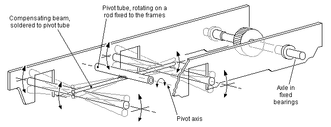 Figure 38 Compensated 0-6-0 with fixed axle
15 0-6-0, 0-4-2, 2-4-0, 2-2-2, Co bogie
15.1 Introduction The next group to be considered are those locos having three axles, and this group is probably the one where there are the greatest variety of possible approaches and solutions.
15.2 Fixed axle rigid beam configurations Of the 3-axle group, the following types can have one fixed driving axle:
- 0-6-0 (or Co bogie) driving on either leading or trailing axle;
- 0-4-2 driving on the leading axle;
- 2-4-0 driving on the trailing axle.
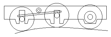 (a) Hump in track (exaggerated)
 (b) Hollow in track (exaggerated)
Figure 39 Compensating action of 0-6-0
Figure 38 shows an 0-6-0 with the drive taken on the right-hand end axle, this axle being in fixed bearings. The centre and left-hand axles rotate in hornblocks that are allowed vertical movement, and bear against the ends of a compensating rigid beam mounted on the longitudinal centreline of the chassis, the pivot point of the beam usually being equidistant from each axle.
The locations where the beam contacts the centre and left-hand axles are secondary suspension points. Secondary suspension points do not need to be within the triangle formed by the primary suspension points, although the one nearest the fixed axle always will be (see figure 41).
Figure 39 shows how the beam allows the wheels to move to cope with humps and hollows in the track; the two axles controlled by the beam are also free to rock laterally to overcome any track warping encountered.
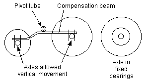 Figure 40 2-4-0 and 0-4-2: basic arrangement
If figure 38 is applied to an 0-4-2 and 2-4-0, one of the compensated axles will be the carrying axle, and figure 40 shows how the beam in this case is stepped to take up the difference in height between this axle and the coupled axle. For 2-4-0s and 0-4-2s, the carrying wheels can have their bearings in the main chassis frame; a little sideplay either on the carrying wheels or the middle axle should be provided, since the total wheelbase is about the same as corresponding 0-6-0 types.
[Contents]
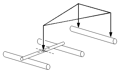 Figure 41 Compensated 0-6-0: principle of weight distribution
15.3 Weight distribution and stability for rigid beam fixed axle configurations Figure 41 shows how the three primary suspension point triangle applies to an 0-6-0, 2-4-0, 0-4-2 or Co bogie compensated with a single rigid beam as per figure 38 (or figure 40). The loco weight is carried on the three suspension points, two being on the fixed axle and the other one being on the pivot point of the compensating beam. (Note however that the effective wheelbase as far as weight distribution is concerned is shortened compared to that of the prototype.)
- For the loco to have any kind of stability, the centre of gravity must lie within the triangle. Good stability requires the centre of gravity to lie in the 'stable' area of the triangle, as shown in figure 6, but such a placement will require putting more weight onto the fixed axle at the expense of the other two.
- Equal weight distribution to the three axles requires the loco centre of gravity to lie one-third of the distance from the beam pivot point to the plane of the fixed axle (see figure 42(a)), but such a placement will make the centre of gravity uncomfortably close to the unstable area of the triangle, since the loco body weight will be prone to tip over sideways around the beam pivot point and lift one side of the fixed axle into the air.
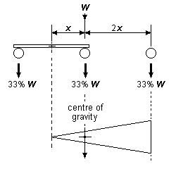
(a) Good axle weight distribution, compromised stability
|
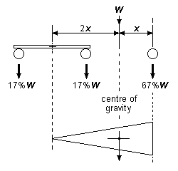
(b) Good stability, compromised axle weight distribution
| |
|
Note: The example shown has equally-spaced axles. Weight percentages are given to the nearest integer.
Figure 42 Compensated 0-6-0: good stability and good weight distribution are incompatible | ||
For an 0-6-0, the two objectives of maximising stability and achieving an equal weight distribution between the three axles are therefore generally incompatible if using a single compensating beam. These objectives are illustrated in figure 42.
For an 0-4-2 or 2-4-0, a different consideration applies, as we are unlikely to want an equal weight distribution between axles; indeed, it is desirable that a majority of the weight should be on the coupled wheels, and moreover, as only four coupled wheels are involved, an equal weight distribution between the two coupled axles is also desirable. Typically, we might be looking for between 35% to 40% of the loco weight on each of the coupled axles, and the remaining 20% to 30% on the carrying axle. As before, the proportion of weight carried by the coupled and carrying wheels will be in direct proportion to the distances between the pivot point and the axles involved, the greater weight being put on the axle nearer to the beam pivot point. If the pivot point of the compensating beam is moved further towards the carrying axle:
(a) the loco will become slightly more stable laterally for a given centre of gravity;
(b) less drawbar pull will be available at the compensated coupled wheels, since more engine weight is now placed on the carrying wheels.
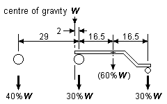
(a) Centre of gravity placed as prototype, beam pivoted about its mid-point |
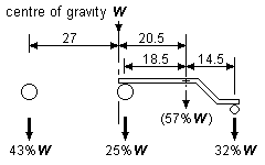
(b) Beam pivot moved toward carrying wheel |
|
|
Note: The example in the figure shows the axle spacings and centre of gravity of a prototype GWR 0-4-2T loco.
Figure 43 Compensated 0-4-2 and 2-4-0: both stability and coupled axle weights are compromised | ||
In the cases of an 0-4-2 or 2-4-0 therefore, the exact point of pivoting is thus a compromise; greater stability being gained by moving the pivot point towards the carrying wheels, but at the expense of less traction available from the compensated coupled axle. There is again a contradiction between achieving good stability and equal coupled axle weights. The dimensions and the centre of gravity used in figure 43(a) are based on a real prototype, and the effect of the beam on the weights on the axles illustrates the dilemma. If the pivot point of the beam is moved 2mm further toward the carrying axle, as in the example of figure 43(b), there will be a marginal increase in stability, but the difference in weights between the coupled wheels becomes even greater. In both cases there is a disparity between the amount of loco weight available for each coupled axle.
[Contents]
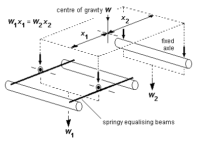 Figure 44 Fixed axle and springy equalising beams 0-6-0
15.4 Fixed axle and spring arrangements If springs are used for two adjacent axles of an 0-6-0, 2-4-0, 0-4-2 or Co bogie, we can dispense with the three-point suspension principle. Figure 44 shows an 0-6-0 using two springy equalising beams on either side of the chassis independently pivoted about their midpoints. The suspension for this chassis, taken as a whole, is now four point suspension.
The weight of the loco is taken on the four points, and the equalising beams ensure that the weight on the pivots is shared between the two axles they bear on. The equalising and cushioning characteristics of the springy beam will cope with humps and hollows in the track and any track warping encountered. It should be stressed however that the arrangement is four point suspension, and the chassis will not be as adept, in accommodating severe track irregularities, as a three-point suspended one.
In such a chassis, it would be usual to drive the fixed axle, as this makes things easier from the point of view of mounting the gearbox and motor, but the drive could be on any of the axles.
In terms of weight distribution and stability, the longitudinal weight distribution of figure 44 is exactly the same as a compensated 0-6-0, with the distribution of loco weight between the suspension points following the principle of moments as usual; now however there is the considerable advantage that no triangle is involved, and thus:
- for a given centre of gravity, transverse stability is far better than a compensated 0-6-0;
- greater latitude can be taken on the placement of the model centre of gravity.
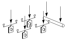 Figure 45 Fixed axle and individual springs arrangement
Individual hornblock springs can be substituted in place of the springy equalising beams, as shown in the example of figure 45, and this six-point suspension arrangement allows the longitudinal weight distribution to follow that of the prototype: for equally spaced axles for example, a loco centre of gravity above the middle axle will result in each axle getting one third of the loco weight. These potential advantages however must be set against the practical difficulties involved in getting the spring tensions correct so that the whole loco sits level with respect to the track.
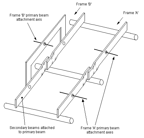 Figure 46 0-6-0: example of rigid beam suspension for all axles (not recommended)
15.5 Rigid beam configurations without a fixed axle Figure 46 shows frames of an 0-6-0, and comparison with figure 38 shows how different the arrangement is: we now encounter multiple primary beams, since with the loss of a fixed axle all three primary suspension points function as beam pivots. Two beams are pivoted from frame 'A', both of which bear on the middle axle hornblock. On frame 'B', two secondary beams are pivoted on a primary beam, the secondary beams again both bearing on the middle axle hornblock. In this arrangement the beams are on each side of the engine, and each axle is controlled in its movement at both ends. In terms of both weight distribution and stability, the arrangement shown in figure 46 is highly undesirable, and is not recommended, as the loco centre of gravity placement is critical.
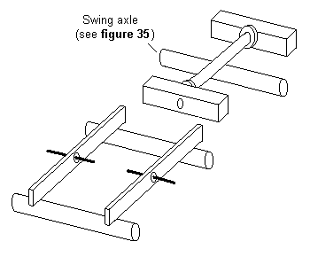 Figure 47 0-6-0: rigid beam suspension for all axles using 'swing axle' arrangement
A simpler and better arrangement for the fully compensated 0-6-0 (and in this version, very suitable for an 0-4-2T or 2-4-0) is shown in figure 47, where one suspension point is provided by a 'swing axle' (see figure 35), while the other two suspension points are given by the frame attachment points of the primary beams on both sides of the other two axles. The beams must be able to pivot independently of each other.
The arrangement shown in figure 47 is particularly useful for six-wheeled tenders not using the 'weighted tender' arrangement, and is perhaps the most suitable system to be used in a 2-2-2, where the driving axle cannot be fixed.
[Contents]
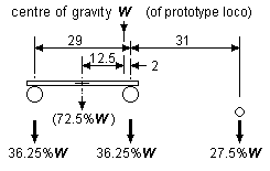 Figure 48 Example of improved weight distribution for 0-4-2T
Figure 48 is an example of an 0-4-2T where the loco centre of gravity adopted is exactly the same as that used in the single beam arrangement of figure 43, but now showing the weight distribution obtained when using the suspension arrangement of figure 44. In this new arrangement, both driving wheels now have an equal division of weight, and the proportion of the loco's total weight available for the coupled wheels is also greater compared to that of one of the arrangements in figure 43.
(a) Individual leaf springs
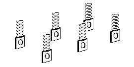
(b) Individual coil springs
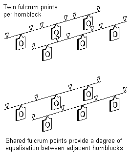
(c) Continuous springy beam

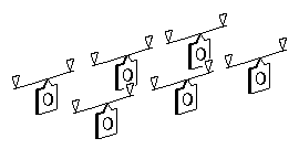
(d) Example of lessening the strength of the middle axle spring
Figure 49 Springing on all axles for a three-axle loco or Co bogie |
15.6 Springing for all axles The three-axle loco is the most common steam wheelbase configuration, but is probably the most difficult to reproduce in fully sprung terms in small scale models.
Figure 49(a) shows an example of a fully-sprung chassis for the classical 0-6-0 prototype arrangement, where the weight of the loco bears down on each individual hornblock at the midpoint of a spring beam supported by two simple supports. The spring beam bears up against its support points, but is not rigidly attached to them. (The cantilever style of spring shown in figure 12(b), where one end is rigidly fixed to the chassis frame, is a possible alternative, but extremely difficult to set correctly.) A coil spring equivalent is shown in figure 49(b).
Further variations are shown in figure 49(c), where the spring beam is a continuous one, which has the practical advantage that different gauges of beam can be tried in such a chassis fairly easily, in order to experiment to find an optimum combination of overall loco stability and dynamic performance over track irregularities. Depending on the strength of the beam, the wheelbase dimensions involved, and the weight of the loco, a degree of equalisation between the hornblock movements between adjacent axles may now be achieved, particularly in the second example shown where fulcrum points are shared between adjacent hornblocks. The setting out of fulcrum points for continuous springy beams is complex, and is not addressed by this Digest (see annex 9).
Because more wheels are involved, longitudinal stability in the above arrangements will be better than that for a fully sprung 0-4-0, but a fully sprung 0-6-0 can be difficult to balance correctly whilst keeping the loco level with the track and at the correct drawbar height. To alleviate these effects, a possible dodge is to arrange for the springs on the outer axles to be slightly stronger than the one on the middle axle, and this is achieved by either making the middle axle spring weaker (by use of a thinner wire, for example) or making the length of the middle axle spring marginally longer than the outer two. See figure 49(d).
It should be stressed that very slight differences in spring strengths, and very slightly differences of spring length, for example, can have a very considerable effect on the weights exerted by each axle. Moreover, if the springs are too strong, the loco will not traverse uneven track correctly, and if the springs are too weak, the loco will display undesirable dynamic characteristics.
In the case of a Co bogie, longitudinal stability is a completely different matter compared to that of a three-axled steam loco, since the stability of Co bogie has to be considered in relation to its other bogie as part of a whole loco. In respect of the principle of weight suspension, a fully sprung Co bogie is therefore far more viable than the equivalent three-axled steam loco.
[Contents]
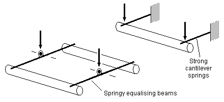 Figure 50 Springing on all axles for a three-axle loco using springy equalising beams
For steam locos, a pragmatic alternative to a complete set of individual springs is by using two springy equalising beams between adjacent axles, with the third axle being supported by stiff springs. See figure 50. In effect, this arrangement is equivalent to that of the fixed axle system in figure 44, except that the fixed axle is replaced by one that is cushioned by springs. Note however that in the case of figure 50 the longitudinal weight distribution follows that given in figure 44, because the effective wheelbase in respect of weight distribution is shortened compared to that of the prototype, and thus the placement of an equal amount of weight on each axle will be more constrained compared to the arrangements shown in figure 49.
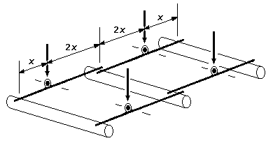 Figure 51 Three-axle quadruple springy equalising beam arrangement
A variation of the use of springy equalising beams is shown in figure 51, where four springy beams are used. Each beam is pivoted at one-third of the distance from the outer axle to the middle axle, and each beam bears on the middle axle. If the centre of gravity is above the middle axle, the pivoting point means that the axles will be equally loaded. Longitudinal stability in this four-point suspension is good, and transverse balance is excellent.
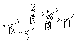 Figure 52 Suggested spring arrangement for a 2-2-2
For a 2-2-2, figure 52 shows how 4 comparatively strong spring beams can provide the longitudinal and transverse stability to the chassis, with coil springs for the middle driven axle. If it is chosen correctly, a coil spring will exert a more consistent force over a greater vertical deflection distance compared to a typical springy beam.
[Contents]
|
|
16 Additions to the basic coupled wheelbase: pony and radial trucks
16.1 Introduction Although wheelbase configurations such as 2-6-2Ts and 2-6-4Ts can be built with rigid beams throughout, the arrangement of beams required is necessarily quite complex. Engines such as 4-6-2s and 2-8-0s can be suspended as 4-6-0s and 0-8-0s respectively, since in these cases the longitudinal balancing problem is not so acute. Many modellers therefore choose to use one of the forms of suspension for a basic 0-6-0 or 0-8-0 for such 'large' engines, where adequate adhesive weight can be put on the coupled drivers, together with pony trucks sprung (either coil or leaf) from the chassis frame.
16.2 A variety of approaches Pony trucks can be dealt with in a variety of ways: figure 53 is the most basic form, where weight is added sufficient to keep the pony truck wheels on the rails. The weight is unsprung in this rigid truck, and does not detract from the adhesive weight on the driving wheels given by the weight of the loco body.
For lightly-weighted pony trucks, figures 54 and 55 show single-spring arrangements. In the case of figure 54, the spring provides combined downward and centralising (side control) functions, and its setting is therefore somewhat of a compromise. To minimise the tipping effect as a result of the sideways component of the force of the spring when the pony truck encounters a curve, the spring should bear on the pony truck frame below the axis of the axle.
Figure 56 is a variation of the coil spring application for heavier locos, but the springs will need to be chosen carefully to obtain the right combination of vertical and centralising forces. A better and more adjustable solution is shown in figure 57, where two independent springs bear onto each side of the pony truck, and where a horizontal centralising spring is arranged so that it does not interfere with the vertical movement of the pony truck.
Separate sprung hornblocks on both sides of a pony truck can be incorporated: the space typically available around pony trucks means that leaf springs will be required – see figure 58. In this case, the vertical movement of the axle with respect to the loco chassis is a result of the combined effects of the individual hornblock springs within the pony truck frame and the downforce spring between the pony truck frame and the loco chassis.
For very heavy pony and radial trucks, where a complete separation of vertical and side control forces is desirable, a rubbing plate arrangement is shown in figure 59.
In all cases of sprung pony or radial trucks, the vertical force exerted on the track by the pony or radial truck will be the same as that applied upward to the loco chassis, i.e. the force will detract from the overall adhesive weight on the driving wheels. The springs of pony and radial trucks therefore need to be set with some care: ideally, the springs should be 'pre-loaded' so that, on level track, the springs are acting near to their mid-point of compression – this will ensure that the springs exert a reasonably consistent force when encountering bumps and dips in uneven track. Coil springs can usually be pulled or snipped to provide a suitable length and strength of movement. For leaf springs, the pre-load is easily adjustable by bending the wire, and its strength can be varied by choosing a different wire diameter. Be prepared to experiment.
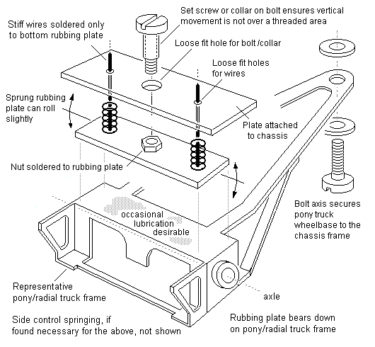 Figure 59 Rubbing plate arrangement for heavy pony/radial truck
[Contents]
17 4-4-0, 0-4-4
17.1 Introduction The main problem with these locos is not where to put the beams or the springs, but how to get the weight distributed effectively.
It has already been noted in the 0-6-0 cases that there can be a penalty to pay in terms of weight distribution and stability if using a single compensating beam. These penalties become more severe with a 4-4-0 and 0-4-4.
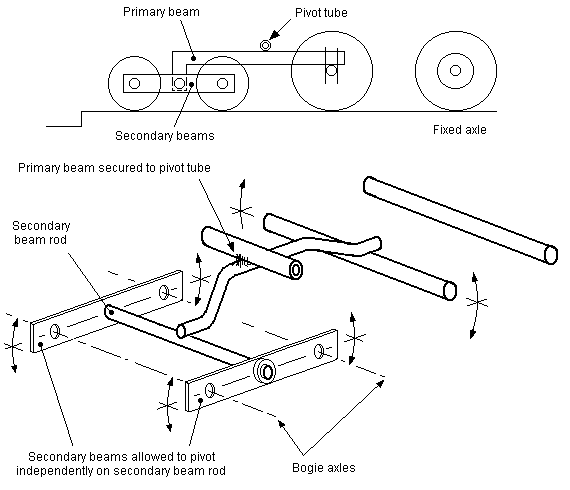 Figure 60 4-4-0 and 0-4-4: principle of fixed axle arrangement with rigid beams
17.2 Fixed axle arrangement with rigid beams The principle of the fixed axle 4-4-0 or 0-4-4 is shown in figure 60, where the fixed axle is at one end, and a primary beam between the other coupled axle to the bogie centreline. The bogie has secondary beams allowing full compensation of the bogie itself. The three primary suspension points are the two on the fixed axle and the other one being the pivoting point of the primary beam.
The sequence of events in the action of the suspension, in encountering a sudden drop in a rail or the track as shown in figure 60 (as might be present at a baseboard joint, or example) is as follows:
- Leading bogie wheel is pressed down over drop by weight of engine, the weight acting through the primary beam pivot. Bogie side frame pivots around rear bogie axle, primary beam pivots around the leading coupled axle.
- Rear bogie wheel is pressed down over drop in a similar way, bogie side frame pivots around front bogie axle, primary beam again pivots around leading coupled axle.
- Leading coupled axle is pressed down over drop, primary beam pivots around the bogie centreline.
- Rear coupled axle is pressed down over drop by engine weight, primary beam pivots around its pivot.
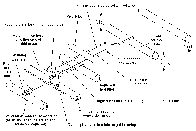 Figure 61 4-4-0: Mike Sharman arrangement
The application of the principle of figure 60 to a model locomotive requires constructional modifications to enable a bogie to guide the loco into curves. Figure 61 shows Mike Sharman's arrangement for a 4-4-0. The primary beam has a rubbing plate soldered to its forward end, which bears upon a rubbing bar fixed to the central member of the bogie. The bogie is itself compensated by the action of the swivelling bush holding the front axle tube. This swivelling bush is held on the central bogie member by washers, thus fixing the bogie wheelbase. The bogie rubbing bar incorporates a hole both sides of which are washers soldered to a spring wire passing through the hole. The whole bogie can thus rotate about the axis of the wire. The other end of the wire spring is fixed to a convenient point on the chassis near to the front coupled wheels, which both holds the bogie wheelbase relative to the coupled wheels, and exerts a centralising bias on the bogie, which, when entering a curve, will cause the rest of the loco to follow.
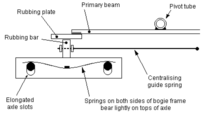 Figure 62 Slotted bogie axle arrangement
A simpler solution for the bogie is to use elongated slots for the bogie axles, with sprung wires bearing on the axles on both sides of the bogie frame (see figure 62). The axles normally lie at the top of their slots, and the springs depress the axles when depressions in the track are encountered.
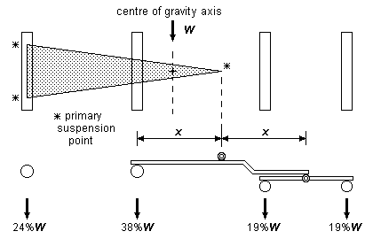
Note: The axle spacings and centre of gravity in the above figure are taken from an LNER G5 0-4-4T, and are drawn to scale.
Figure 63 Example of weight distribution for an 0-4-4T with fixed axle |
Figure 63 shows the weight distribution for an example of an 0-4-4T with a fixed axle, compensated as per figure 61, and where the pivoting point of the primary beam is halfway between the non-fixed coupled axle and the bogie centre. The weights on the coupled axles are reasonably similar (a slight change to the position of the primary beam pivot point could make them identical if this was felt necessary), but it is the transverse stability of the arrangement that is of concern, as the centre of gravity line is uncomfortably close to the 'area of instability' of the three-point triangle. A lot more weight would need to be added to move the centre of gravity toward the fixed axle to improve the transverse stability, but in a real model, it may not be possible to put this required weight in the right place, and thus the scope for transverse stability improvement in 0-4-4Ts is likely to be marginal with this suspension arrangement, and it would also be at the expense of making the coupled axle weights dissimilar. For 4-4-0s, the centre of gravity can be taken back toward the rear fixed driver by use of the weighted tender arrangement (see 12.2), but this will also increase any dissimilarity of the coupled axle weights.
The overall situation is not particularly satisfactory; there are better ways to suspend these wheel configurations.
[Contents]
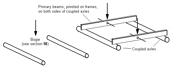 Figure 64 4-4-0 and 0-4-4 without a fixed axle
17.3 Arrangements without a fixed axle A 4-4-0 with suspension for all axles is shown in figure 64, and here the bogie centre forms one of the primary suspension points, with the pivoting points of the primary beams on both sides between the coupled axles making up the other two of the three primary suspension points. This arrangement is the same as that employed in a bogie coach using beam-compensated CCUs. Neither coupled axle is fixed in this arrangement, and we therefore need a gearbox to transmit the drive from the motor (see 12.5).
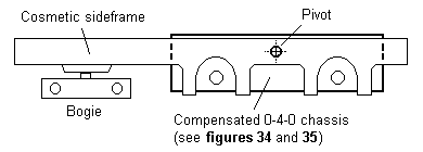 Figure 65 4-4-0 and 0-4-4: suspension for all axles using swinging fixed axle 0-4-0 subchassis
A dodge to get round the need of a floating gearbox is to use a compensated 0-4-0 chassis (see figures 34 and 35) which is itself allowed to swing in a transverse pivot, the pivot point being between the coupled wheels and slightly above the centreline of the coupled axles (see figure 65). The outer sideframes are in this case merely cosmetic and should be provided with oversize slots to clear the coupled axles. A useful feature of figure 65 is that either 'bogie' can tilt freely without adversely affecting the height of the buffer beams.
An obvious difference between the coach and the above arrangements is that the coupled axle subchassis cannot rotate to follow curves (unless of course your prototype loco has no splashers and/or there is enough clearance to provide the necessary degree of rotation). We must therefore provide the bogie with a certain amount of both rotation and controlled sideplay (see section 18).
Although the transverse stability given by the rigid beams in figure 64 is better than that of the fixed axle arrangement in figures 61 and 63, the two primary rigid beams on either side of the frame in figure 64 can be replaced by equalising springing ones, which will cushion the loco weight on the coupled axles. Springy equalising beams can also be used in the bogie (see figure 69). The use of springy beams between the coupled axles does away with the need to consider the transverse stability effects of the three-point triangle, although it is advisable that the bogie frame should retain the ability to pitch and roll in relation to the rest of the loco chassis, because the degree of independent vertical axle movement is limited with springy equalising beams.
This point is explored further in section 21 on diesels and electrics. The use of individual leaf springs on a 4-4-0 or 0-4-4T makes such locos equivalent to 0-8-0s, Bo-Bos and DMUs/EMUs, and will therefore be considered in the sections specific to those types.
[Contents]
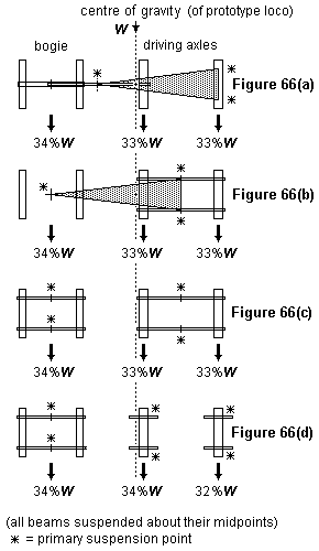
|
Suspension: figure 61 Longitudinal stability: Good Transverse stability: Poor (a) Rigid beams Suspension: figure 64 (either with rigid or springy equalising beams), or figure 65 Longitudinal stability: Good Transverse stability: Reasonable (b) Equalising beams for driving wheels Suspension: Springy equalising beams for coupled axles and bogie axles (figure 77(c)) Longitudinal stability: Good Transverse stability: Excellent (c) Springy equalising beams for driving and bogie wheels Suspension: Individual coil or leaf springs for coupled axles and springy equalising beams for bogie Longitudinal stability: Good Transverse stability: Good (d) Individual coil or leaf springs for driving wheels |
|
Note: The axle spacings and centre of gravity in the above figure are taken from a GWR Bulldog 4-4-0, and are drawn to scale.
Figure 66 Comparison of different suspension systems for the same 4-4-0 loco | |
17.4 Weight distribution and stability for 4-4-0s and 0-4-4Ts Weight distribution for 4-4-0s and 0-4-4Ts is always a problem, and while we have enabled all wheels to carry weight, getting the right proportion on each axle or group of axles requires careful consideration for each individual loco and the particular suspension method(s) chosen. The exact positioning of beam pivot points will have an important effect on both stability and drawbar pull, as will the centre of gravity. Figure 66 compares a variety of suspension systems using an example of a real 4-4-0 loco with a prototypical centre of gravity. For this particular loco, note how the different model suspension systems give axle weight percentages almost identical to the prototype values.
[Contents]
18 Additions to the basic coupled wheelbase: bogies
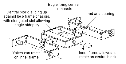
Note: The outer bogie frame, not shown in the diagram, is rigid, and its central stretcher is attached to the central block.
Figure 67 Example of single-point suspension rigid beam bogie |
18.1 Introduction Bogies have been mentioned in the specific contexts of figure 61 and figure 62. For rigid-beamed locos, they usually form the distant point of the 3-point triangle. An example of a rigid-beamed bogie providing a single point of suspension to a chassis is shown in figure 67.
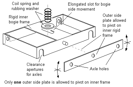 Figure 68 3-point compensated bogie with central spring
Figure 68 shows an example of a bogie with a single coil spring bearing down from the loco chassis. The bogie itself is 3-point compensated, with one of the points being the rocking side plate fitted to one side of the bogie only. The strength and the extent of the deflection of the coil spring needs to be chosen with care if it is to properly support the chassis, and the spring should ideally be fitted with a screw adjuster if both a reasonable downforce and correct chassis rideheight is to be achieved.
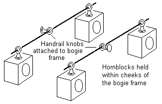 Figure 69 Equalising springy beam bogie
Figure 69 shows a bogie with 2 springy equalising beams supported at their midpoints to the bogie frame. The bogie frame does not need any further springing between it and the loco chassis. The plain hornblocks are carried in U-shaped cheeks of the bogie frame, to prevent any unwanted transverse movement within the frame.
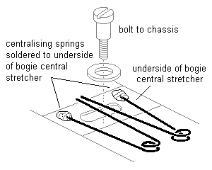
(a) 'Scissors' arrangement
|
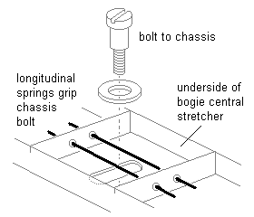
(b) Longitudinal springs arrangement
|
| Figure 70 Sideplay control for loco bogies | |
18.2 Side control for bogies Most loco bogies need a small amount of transverse sideplay with respect to the loco chassis. This is usually achieved by providing an elongated slot in the central bogie stretcher through which the bogie is attached to the loco chassis. Figure 70 shows examples of how centralising springs can be arranged within the bogie to grip either side of the bogie fixing.
[Contents]
19 4-6-0, 2-6-0, 4-4-2
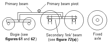 Figure 71 4-6-0: principle of fixed axle arrangement
19.1 Introduction As the number of axles increases, the 'three-point' triangle for rigid beam chassis with a fixed axle at one end becomes narrower, and thus the problems of transverse stability now become acute for the more complicated asymmetric wheelbase configurations.
The use of individual coil or leaf springs becomes more viable as the number of axles increases, since the effects of the sensitivity of individual springs within the total chassis become less marked. Leaf springs will however be more predictable in their behaviour compared to coil springs, and leaf springs are more adjustable than coil springs.
19.2 Fixed axle arrangements Figure 71 shows a 4-6-0, and as well as the bogie compensation we encounter a further secondary beam, which Mike Sharman calls a 'link beam', this time between the two leading coupled axles. The primary beam in this case extends from the centre of this secondary 'link' beam to the bogie centreline. In practice, owing to the need to allow the bogie to rotate and move sideways slightly, this 4-6-0 could be arranged by using a rubbing plate and centralising spring arrangement shown for the 4-4-0 in figure 61.
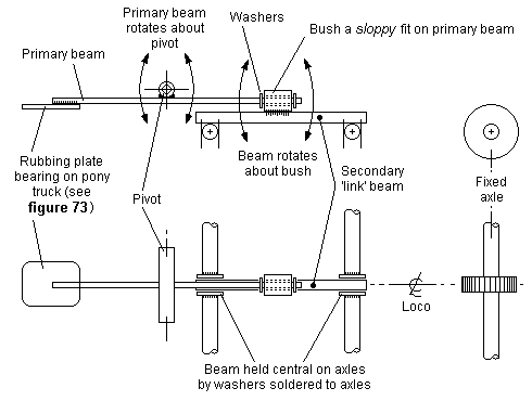
(a) Mike Sharman arrangement
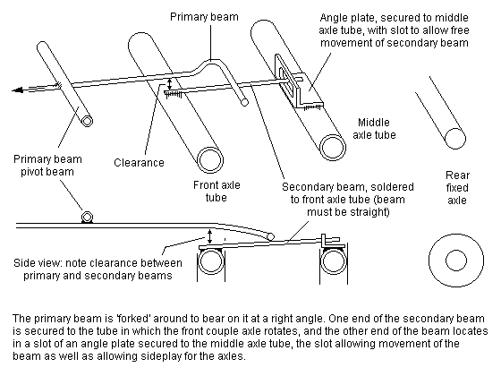
(b) Alternative method of arrangement
Figure 72 2-6-0 |
|
|
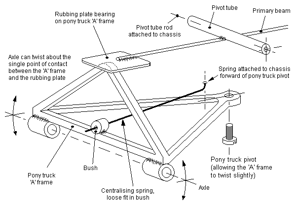 Figure 73 Pony truck arrangement
|
Mike Sharman's arrangement for a 2-6-0 is shown in figure 72(a), and includes a primary beam with rubbing plate in a similar manner to that shown for a 4-4-0 in figure 61. The rear end of the primary beam is attached via a trunnion to the secondary 'link' beam, which bears on the front two coupled axles. (An alternative arrangement, which avoids the need to attach the primary and link beam is shown in figure 72(b).) The pony truck is of 'A' frame construction and is pivoted from a point as far back along the chassis as possible to give the best radius of arc, and the centralising action is again provided by a spring wire, one end of which is soldered to the chassis, the other end sliding in a bush on the pony truck frame (see figure 73).
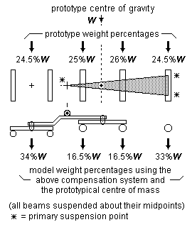
Note: The axle spacings and centre of gravity in the above figure are taken from an LMS 'Black 5' 4-6-0, and are drawn to scale.
Figure 74 Weight distribution and stability for fixed axle 4-6-0 |
19.3 Weight distribution with fixed axle The weight distribution for a typical mixed-traffic 4-6-0 is shown in figure 74, and it can be seen that, even if the centre of gravity of the model were to be moved compared to the prototype location (by using a weighted tender, for example), there would still be a considerable disparity between the weights on the coupled drivers, and the transverse stability is still severely compromised.
[Contents]
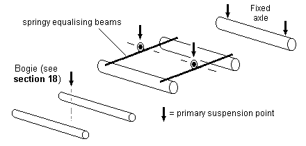
(a) Fixed axle at rear of loco
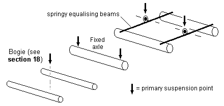
(b) Fixed axle on front coupled axle
Figure 75 4-6-0 and 2-6-0: uses of springy equalising beams
19.4 Use of springy equalising beams, and alternatives to the conventional fixed axle position The transverse balance problem inherent in figure 71 will be alleviated by using twin springy equalising beams between the front two coupled wheels, and springing the front bogie (for a 4-6-0) or pony truck (for a 2-6-0). This arrangement (see figure 75(a)) uses five primary suspension points, and is equivalent to figure 44 with the addition of a further suspension point for the bogie or pony truck.
A less conventional approach using springy equalising beams is shown in figure 75(b), with the front coupled axle being the fixed one. If the springy equalising beams are too weak, there is a danger that the dynamic effect of the front bogie/pony spring could be to rock the loco about the fixed axle axis onto the rear drivers. The strength of the spring on the bogie or pony truck will need to be chosen to avoid this situation. Although there is a degree of tolerance as to where the overall loco centre of gravity can lie, this placement cannot be divorced from the question of how strong the springs are.
For a 4-6-0 or 2-6-0 using either of the arrangements in figure 75, or where figure 75 is used for 2-6-2Ts or 2-6-4Ts for example, it is recommended that a good balance and stability be obtained over the coupled axles first, and for the bogie/pony truck spring to be chosen so that the bogie/pony maintains good trackholding, but is not so strong as to significantly upset the balance of the coupled drivers.
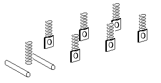 (a) Coil springs
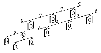
(b) Continuous and equalising springy beams
Figure 76 Springing for 4-6-0s
19.5 Springing The overall wheelbase length for 4-6-0s and 4-6-2s is relatively long. In such engines, the bogies and pony trucks need to be sprung for consistent and reliable trackholding. The loco weight available for the coupled wheels is reduced by the force that the bogie and pony exert on the track, and therefore obtaining the right proportion of weight over the coupled wheels can be difficult: overall longitudinal stability will improve if the springing on the bogie and pony is strong, but will result in reduced weight, and therefore traction, on the coupled wheels.
Spring-assisted hornblocks (see 8.3) have low springrates compared to equivalent leaf springs, they but cannot exert the correct downforce: their use may therefore provide a pragmatic way of suspending the coupled axles, but the chassis will be riding with the characteristics of a rigid one, since spring-assisted hornblocks will have their springs fully compressed most of the time.
Proper (non-spring-assisted) coilspring hornblocks will provide a more satisfactory solution compared to spring-assisted ones. Individual or continuous springy beams are an attractive alternative, and their behaviour is somewhat more predictable at small deflection distances compared to coil springs. Figure 76 gives two different approaches to springing a 4-6-0.
[Contents]

(a) Fixed axle suspension with rigid beams (not recommended)
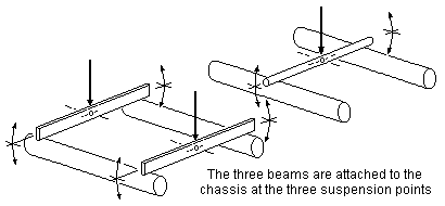
(b) Rigid beam suspension for all axles
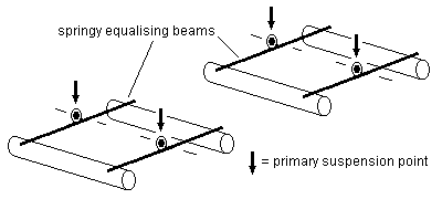
(c) Springy equalising beams
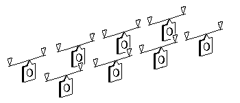
(d) Individual beam springs
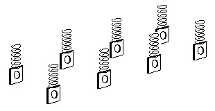
(e) Individual coil springs
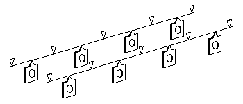
(f) Continuous springy beams
Figure 77 Different approaches for an 0-8-0 |
20 0-8-0, 2-8-0, etc.
20.1 Introduction Although eight- and ten-coupled wheelbases can be built with rigid beams and a fixed axle, it is not recommended. Not only is the arrangement of beams complex in construction, there will be very poor transverse stability and no chance of any kind of equal weighting for the coupled axles.
For these larger engines, springy equalising beams, continuous springy beams, spring-assisted hornblocks or sprung individual hornblocks provide far better approaches than the use of rigid beams.
20.2 Rigid beam arrangements Two alternative arrangements for an 0-8-0 are shown: figure 77(a) shows the conventional system with a fixed axle at one end, while figure 77(b) shows suspension for all axles, with beams on each side of the chassis between two axles and another central beam between the other two axles. Figure 77(b) is exactly the same as that employed in a coach fitted with CCUs.
Figure 77(b) can be used for a 2-4-2T, but the beams will need to be joggled in a similar manner to that shown for the 2-4-0 (see figure 40) to cope with the difference between the axle centreheights, and the pivoting axes of the beams need to be chosen to obtain the desired proportion of the loco weight on the coupled axles.
20.3 Springs Figure 77(c) shows the use of four springy equalising beams for an eight-coupled chassis. The system is four-point suspension, has excellent transverse and longitudinal stability, and can achieve equal loading of the coupled axles if the loco centre of gravity line bisects the two middle axles. This arrangement could be used on a ten-coupled wheelbase, with the four equalising beams bearing on the outer axles, with the centre one sprung with a coil or leaf spring.
Figures 77(d) and 77(e) show individual beam and coil springs, and figure 77(f) is the continuous springy beam approach.
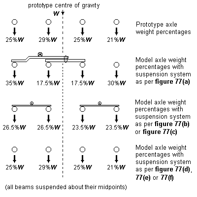
Note: The axle spacings and centre of gravity in the above figure are taken from an LNWR G2 0-8-0, and are drawn to scale.
Figure 78 Weight and stability for an 0-8-0 |
20.4 Weight distribution and stability Using an example of a real loco, figure 78 compares the static weight distributions and stability for the various configurations of figure 77.
[Contents]
21 Specific matters on drive bogies
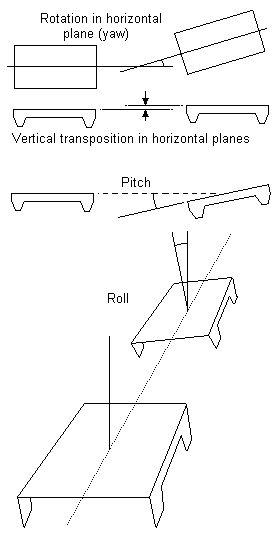 Figure 79 Bogie articulation in diesels, electrics, DMUs/EMUs
21.1 Introduction Like a coach bogie, a single drive bogie cannot be treated in isolation: it has to be considered together with another bogie (possibly also powered) in the chassis taken as a whole.
The wheelsets in the two bogies of a chassis need to:
- be able to articulate with respect to each other, in order to cope with track irregularities;
- provide transverse stability to the loco body.
Most diesels, electrics, DMUs and EMUs tend to be well balanced longitudinally by the nature of their design, and thus overall longitudinal balance is not usually a problem in models.
In addition to the wheels within a bogie needing to articulate with respect to each other (as for any other 0-4-0 or 0-6-0), the four ways in which a bogie needs to articulate with respect to another bogie are shown in figure 79.
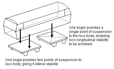 Figure 80 Transverse and longitudinal stability
21.2 Use of three-point suspension principle In three-point suspension, transverse body stability is achieved by making the body rest on one bogie at two points in a transverse vertical plane. For the other bogie to be able to articulate correctly with respect to the first means that the second bogie can support the body only at a further single point on the longitudinal centreline. See figure 80. The bogies themselves can be equivalent to 0-4-0s (see section 14) or 0-6-0s (see section 15). The three-point triangle constituted by this arrangement is very elongated, and the transverse stability is not as good as that given by multi-point springing.
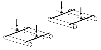 Figure 81 Springy equalising beams in a Bo-Bo
21.3 Use of four-point and multi-point suspension Diesels and electrics etc have inherently good longitudinal stability, owing to the distance between their bogies, and springy equalising beams can be used in the bogies – see figure 81. In practical terms, this could be implemented as shown in figure 69. The equalisation will take care of track irregularities within the length of the bogies themselves, but some consideration will need to be given to the pitch and roll abilities of the bogies as required in figure 79 in order to cope with track irregularities over the whole length of the loco wheelbase.
Individual leaf springs can be fitted to bogies, and although the overall longitudinal stability of the loco will be good, continuous springy beams (see figure 49(c) for example) within each bogie will give an improvement in their roll stiffness, which will help the overall roll stability of the loco as a whole. The spring deflections should be chosen to cope with the required bogie-to-bogie articulations as shown in figure 79.
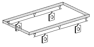
(a) Example of bogie with continuous primary beams but no secondary springs |
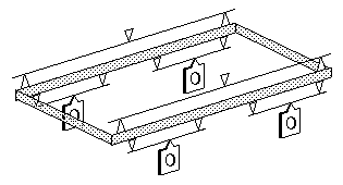
(b) Example of bogie with secondary (bolster) springing and individual primary (axle) springs |
| Figure 82 Representative examples of springy beam model bogies | |
Figure 82 gives examples of model equivalents of prototype bogie springing, using spring beams bearing up against fulcrum points.
[Contents]
Annex 1
Glossary of terms
For the purposes of this section of the Digest, the following definitions apply.
cantilever spring A springy beam secured or constrained only at one end.
centre of gravity The single point where the total weight (as a resultant vertical force of the gravitational attraction by the earth) of a body acts. A force applied to the centre of gravity of an object produces acceleration but no rotation.
compensation A suspension system using a rigid beam or beams acting via the principle of three-point suspension.
equalisation Even or reciprocal balance.
gearbox A rigid structure holding gears in a precise mesh.
lever A simple rigid bar pivoted about a fulcrum (fixed point) that can be acted upon by a force in order to move a load.
moment The turning effect produced by a force acting at a distance on an object, this effect expressed as the product of the force and the distance from its line of action to a chosen point.
pivot A shaft or pin on whose primary axis something turns.
rigid beam A beam exhibiting no appreciable vertical deflection when under vertical load.
springy beam A beam exhibiting significant vertical deflection when under vertical load.
springrate The ratio between the deflection of a spring and the force applied to or by that spring. The springrate is a constant value for any particular spring.
Note: For small coil springs, the springrate is normally considered to be constant only over the central 60% of the deflection range.
statically indeterminate A static situation where the forces cannot be uniquely determined by force balance alone, and where the forces are dependent on structural deflection and elasticity.
swing axle An axle that rotates about the longitudinal centre axis of a loco.
torsion bar A bar that bends along its axis.
trunnion A supporting cylindrical projection or collar on each side of a beam.
[Contents]
Annex 2
How to determine the centre of gravity axis of a prototype loco
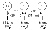
(a) Stage 1: prototype axle weights and dimensions
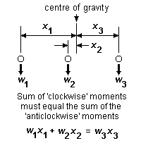
(b) Stage 2: theoretical centre of gravity established
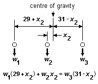
(c) Stage 3: substituting known values
Figure 83 How to determine the centre of gravity of a prototype loco |
If the prototype axle weights are known, the centre of gravity of the loco can be calculated from the wheelbase dimensions using the principle of moments. In essence, the principle of moments states that, for any body at rest, the sum of the moments about any point is zero. (A moment is the product of the weight acting at a point multiplied by the perpendicular distance of that point to any other chosen point.)
Figure 83(a) shows a typical 0-6-0, with the wheelbase dimensions (with 4mm scale equivalents) and hypothetical but typical axle weights. Figure 83(b) shows the projected centre of gravity established. The principle of moments requires that the clockwise sum of the moments about the centre of gravity line must equal the anticlockwise moments about the same line. Figure 83(c) substitutes the known weight and dimensions to determine exactly where the centre of gravity is. In our example:
| w1(29 + x2) + w2x2 = w3(31 – x2) | [sum of clockwise moments must equal the sum of anticlockwise moments] |
| 29w1 + w1x2 + w2x2 = 31w3 – w3x2 | [above equation expanded] |
| w1x2 + w2x2 + w3x2 = 31w3 – 29w1 | [re-arrangement of expanded equation] |
| x2(w1 + w2 + w3) = 31w3 – 29w1 | [further re-arrangement to isolate x2] |
| x2 = (31w3 – 29w1) ∕ (w1 + w2 + w3) | [dividing previous expression to obtain x2] |
As w1, w2 and w3 are all known, x2, the distance of the centre of gravity from our middle axle, can be calculated from the last expression.
The method above can be applied to any loco, regardless of the complexity of its wheel arrangement. In most prototype locos, the addition of water and coal (as appropriate) to tank locos will of course increase the finite axle weights, but in most cases is unlikely to alter the position of the loco centre of gravity appreciably.
[Contents]
Annex 3
The desirability of equal loading of driven axles
Haulage ability is maximised if the weights on the driven axles are equal. Prototype designers were often constrained in their ability to achieve this objective, and similar constraints can apply to models.
Driven axles in models are rotated together (by coupling rods, in steam engines, and via hidden gearing, in most diesel and electric outline models), but the torque distribution is statically indeterminate.
When power is first applied, the elastic system (gears, coupling rods, wheel centres etc.) coupling each tyre to the motor starts to deflect. The torque each wheelset applies to the rail is equal to the stiffness of the tyre/motor system times the deflection. This does not mean that the wheelset stiffest with respect to the motor, i.e. the driven axle, carries the most torque, since the state of the system when the loco started was unknown: at rest, there can be equal but opposing frictional forces between several wheels and the rail.
With the loco underway, the torque delivered to each tyre is equal to the stiffness from the tyre to the motor times the deflection between tyre and motor. The important difference between equally loaded and unequally loaded axle locos occurs when one wheelset starts to slip.
If slipping occurs in one wheelset, the strain (deflection) between that pair of tyres and the motor will relax, reducing the torque being carried by the wheelset. Meanwhile, the strain between the motor and the other tyres will increase. In effect, the load will be rebalanced; the reduction in frictional torque from one wheelset will be balanced by an increase from the others.
This arrangement will be stable only if there is sufficient margin between the frictional torque limit of the other wheelsets and the torque they are actually carrying. For a six-coupled loco, this means that the stable haulage limit is equal to the frictional force produced by only five tyres, i.e. in effect, two axles. The maximum frictional force from a tyre is proportional to the load carried by the wheel. Since the distribution of torque between the wheels is indeterminate, it follows that any of them could slip, and therefore maximum haulage is produced by a loco with an equal weight distribution.
If a wheel starts to slip on a loco with equal weight distribution, there is a fair chance that the other wheels will be able to carry the additional load, allowing a stable redistribution of torque between the axles. If a wheel starts to slip on a loco with unequal weight distribution, the other wheels might be able to carry the additional load, but if it is a heavily loaded wheel that is slipping, this will not be the case, and the other axles will start to slip too.
In other words, the maximum haulage is independent of load distribution, but maximum stable haulage is obtained with equal weight distribution between all wheels.
[Contents]
Annex 4
The effect of drawbar pull
Introduction The drag of a train attached to a loco drawbar produces a couple force on the loco, and has the effect of shifting the loco's centre of gravity slightly. Figure 84(a) shows this couple force in relation to the rail level. This couple has the same effect as a couple of the same magnitude acting with a lever arm over the chassis wheelbase, as is shown in figure 84(b), which results in a redistribution of the axle loads. This redistribution is identical to the effect of shifting the loco centre of gravity.
Note that the height of the loco centre of gravity above the railhead, the wheel size, and the distance of the drawbar point to the wheels do not alter the magnitude of the drawbar couple force.

(a) Drawbar couple

(b) Equivalent couple over wheelbase
F = drawbar pull
h = height of drawbar above rail level drawbar couple force = Fh Figure 84 Drawbar couple |
Example of effect Assuming the height of the drawbar above the railhead is 14mm (for 4mm scale), and using the example of an 0-6-0 with equally weighted and spaced axles over a wheelbase of 62mm, a drawbar pull of 20% of W will produce a drawbar couple force of Fh = W x (20 ∕ 100) x 14 = 2.8W. The adjustment to the W ∕ 3 axleloads on the leading and trailing axles is therefore 2.8W ∕ 62 = 0.048W, i.e. these axleloads change from 0.333W to 0.333 + 0.048 = 0.0381W or 0.333 – 0.048 = 0.285W. In figure 84, if the loco is travelling from right to left, axle 1 would be the lightest loaded, and axle 3 the heaviest loaded.
The change in axleload will depend on the actual drawbar pull. The greater the pull, the greater the effect on the loco axleloads. For a drawbar pull of 20% of W, the axleload change for the example above is approximately 14%. A drawbar pull of 30% of W will produce an axleload change of approximately 20% over the same wheelbase.
The effect of the drawbar couple will be less pronounced the more axles there are, and will be less pronounced if the wheelbase is long.
On a sprung loco, the couple force will have the effect of making one end of the loco dip slightly. (The right-hand end, using the example in figure 84, with the loco travelling from right to left.)
For locos using a single compensating beam on the longitudinal centreline of the chassis, the effective change of centre of gravity arising from the drawbar pull will make the loco more or less stable, according to the direction of travel.
Counteracting the effect of drawbar couple The drawbar couple force has the effect of shifting the centre of gravity back toward the drawbar pull point. There is nothing we can do about this. On a tank loco or diesel etc., where we usually look for a similar performance in either direction of running, it would be unusual for a centre of gravity to be designed so as to favour one particular direction of running. For tender locos however, the design centre of gravity can be placed so that a particular drawbar pull force will produce an equal loading on the driven axles. Using the example of figure 84, the design centre of gravity would be set forward slightly so that, with no drawbar pull present, axles 1 and 2 carry more weight than axle 3.
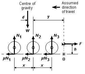 Figure 85 Moment balance for drawbar pull
A more formal way of examining the situation for three driven axles is given in figure 85. Here, there is an equally-spaced wheelbase and a projected centre of gravity at a distance d from the middle axle centreline. The force balance vertically requires that the sum of the axleloads equals the overall weight, i.e. N1 + N2 + N3 = W, and the longitudinal force balance requires (assuming constant velocity of the loco) the drawbar pull to equal the frictional forces (see annex 5) at the interfaces of wheels and rails, i.e., using the simplified notation of three wheels on one rail (rather than 6 wheels on two rails):
μN1 + μN2 + μN3 = F
Moment balance can be taken about any point, but it is convenient to take the moments about point O directly underneath the application point of the drawbar force F. This means we can ignore the frictional wheel/rail forces μN1 etc., as they produce no moment about point O. In figure 85, the sum of the clockwise moment about point O must equal the sum of the anticlockwise moments, i.e.:
N1(y + x) + N2y + N3(y – x) + Fh = W(y + d)
multiplying out the factors, and rearranging, and knowing that N1 + N2 + N3 = W, we get, successively:
N1y + N1x + N2y + N3y – N3x + Fh = Wy + Wd
(N1 + N2 + N3)y + (N1 – N3)x + Fh = Wy + Wd
(N1 – N3)x + Fh = Wd
If we want the loads on axles 1 and 3 to be equal under the effect of drawbar pull, i.e. N1 = N3, then the final line of the equation becomes simply d = Fh ∕ W, which works out to 2.8mm (for a drawbar pull of 20% of W) ranging up to 4.2mm (for a drawbar pull of 30% of W). Real values and real axle spacings can be inserted in the equation to determine the effects of drawbar pull, and the style of calculation is the same for any number of axles.
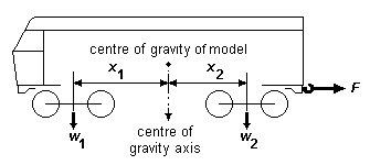 Figure 86 Drawbar pull on drive bogie systems
The methodology can be applied to drive bogie systems, as illustrated in figure 86, although most diesels, electrics, DMUs/EMUs are symmetrical and are expected to perform identically in either direction of travel, and the shift in the effective centre of gravity is extremely small compared to the overall wheelbase of a bogie vehicle.
[Contents]
Annex 5
Friction
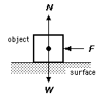 Figure 87 Friction
In figure 87, the force F required to move an object over a surface is proportional to the coefficient of static friction applicable to the two materials involved. The area of contact between the object and the surface is irrelevant. F = μN, where F is the force required to move the object, μ is the static coefficient of friction between the two materials, and N is the normal force (equal to and opposing the weight W of the object). So, if μ is low, not much force will be necessary. Similarly, the higher μ is, the greater the 'grip' of the two materials will be.
Some coefficients of static friction are:
- mild steel on mild steel: 0.74
- nickel on nickel: 1.10
It should be noted that these values apply only for perfectly clean materials: any traces of grease (as would always be present on most models) will reduce the coefficient of friction dramatically – a typical value between greasy surfaces is 0.1.
[Contents]
Annex 6
The effect of curves on the centre of gravity
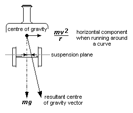 Figure 88 Effective shift of centre of gravity on curves
When traversing a curve (whether superelevated or flat), a loco's centre of gravity takes on a horizontal component owing to the centripetal force. This horizontal component has an influence on where the centre of gravity line intersects the suspension point plane. In effect, the intersection is shifted slightly: see figure 88. For small-scale models, even for those relying on a three-point suspension 'triangle', the effect of this shift is extremely small for reasonable speeds around reasonable curves, and can usually be ignored. In other words, notwithstanding the effects of wheel flanges interfacing with rail, a loco will be no more unstable going round a curve than it is travelling in a straight line. The lower the centre of gravity of the loco, the less any transverse shift of the effective centre of gravity line will be.
Far more relevant is the effective shift of the intersection arising from any excessive canting of the track or any sideplay in either coupled wheels or bogies. In critical cases, e.g. the 0-4-4T example in figure 63, the transverse shift in the effective centre of gravity line on curves could markedly increase the transverse instability of the loco.
[Contents]
Annex 7
How much vertical hornblock movement is necessary?
If you have absolutely level track and perfect wheels, a rigid chassis will run perfectly, and no chassis suspension system is needed. The whole question of whether any suspension system is needed cannot be divorced from how good your track is, or others' track you may encounter. A generally accepted default value in 4mm scale for the necessary vertical movement of a hornblock is 0.5mm above and below the axle datum centreline. If you can build any type of loco chassis that works, you will be able to make track that should not require vertical hornblock movements greater than this. Maintaining good track alignments at baseboard joints is however recognised to be a perennial problem, and a more conservative value of 0.75mm above and below the axle datum centreline could be considered as a safer margin.
The translation of the value of 0.5mm (or 0.75mm) becomes complicated when considering springs, as we want, if possible, a spring to exert a reasonable force throughout such a deflection distance. This requirement is generally incompatible with the other characteristics we desire of springs, so a design springrate and deflection value need to be chosen with care.
[Contents]
Annex 8
Use of more than one fixed axle
Ideally, there should be only one fixed axle at most in any chassis or subchassis. This enables all the other axles to articulate to cope with track irregularities. Most commercial chassis and drive bogies however are likely to feature two or more fixed axles. The following factors will help the viability of such a chassis:
- Track flatness will need to be very good, with an objective of not allowing vertical (or twist) deviations from the level datum greater than 0.25mm over the length of the wheelbase concerned. (This value is recommended for 4mm scale to enable at least part of a 4mm scale flange to keep below the railhead.)
- Particular attention will need to be paid to the good alignment of rail joints.
- The smaller the distance between the fixed axles the better.
- Any non-fixed axles should be sprung, but with a rating such that the axle bears down onto the rail with a force less than that imposed by any of the fixed axles, but not so weak as to allow the chassis to rock over the fixed axle.
- Every advantage should be taken of any slop in the fixed axle bearings to make the wheels bear better onto the rail, for example by the use of pickups acting on top of the wheeltreads, or by springs bearing on the axles or axle bushes.
Increasing the total weight of the loco beyond that necessary for good adhesion but short of overloading the bearings will not decrease the chance of a derailment.
[Contents]
Annex 9
Further reading
Locomotive kit Chassis Construction in 4mm scale, by Iain Rice, Wild Swan Publications (ISBN 1 874103 100)
Etched loco construction, by Iain Rice, Wild Swan Publications (ISBN 0 906867 86X)
Flexichas – a way to build fully compensated chassis, by Mike Sharman
Gear fitting for the modeller, by Mike Sharman
Hal O' the Wynd, by Chris Pendlenton, article in MRJs 28 and 29
Rubber and Leaf Suspension, by Chris Pendlenton, article in MRJ 6
Equalizers for steam locomotives, by Jerry Howell, article in Model Railroader, September 1972
Equations for the deflection of spring beams may currently be found under the heading 'Deflection of beams' on the CLAG website.
[Contents]
© Russ Elliott 2003
Amendments:
- Figures 28(b), 44, 50, 51, 75(a), 75(b), 77(c), 78 and 81 amended 5 June 2009. These amendments changed the attachment of springy beams to transverse pivots from being above those pivots to below the pivots – the mechanical strength of the soldered joint is far better if the load carried by it is a compressive one. (Figure 17(b) also corrected to show correct orientation of fulcrum pivots.)
- figure 88 corrected February 2011
- expression in figure 18 corrected April 2012
| Return to top of page | Safety, privacy and cookies |
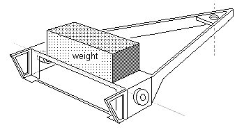 Figure 53 Pony truck weight
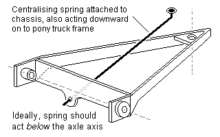 Figure 54 Simple beam spring for pony truck
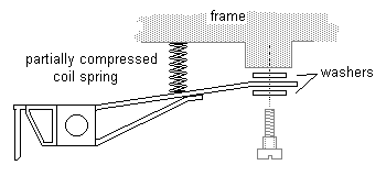 Figure 55 Simple coil spring for pony truck
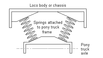 Figure 56 Pony truck springing (for larger locos)
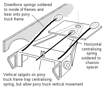 Figure 57 Separation of downward and centralising forces for pony or radial truck
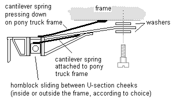 Figure 58 Pony truck with hornblocks