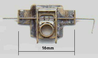
 Gordon Ashton's etched brass loco springing unit fitted with MJT 1/8" bore square bearings: the bearing yoke has two 'ears', and thus the contact with the spring is not a true single point contact, although the ears are close together in relation to the overall span not to effect much difference in the deflection compared to a true single-point contact. The datum height of the spring wire in the above unit can be set by threading it through a choice of holes in the fulcrum span lugs at both sides of the assembly.
photo courtesy Gordon Ashton
Deflection of beams: worked examples for a springy beam with a load between two simple supports
by Russ Elliott
A common commercial configuration of springy beam being used in model locos, coaches and wagons is that of a beam with two simple supports and where the load is between the supports.
The purpose of this page is to provide some examples and worked calculations of the spring deflections for this configuration.
Reference should be made to the Deflection of beams article for meaning of the symbols used here.
Expanding the equations for the beam configurations being considered |
|
Centre-loaded beam, round section steel spring
|
The deflection formula for a springy beam configuration with a centre load between two simple supports is δ = FL3 ∕ 48EI. Assuming the use of a round cross-section spring wire for the beam, substituting the moment of inertia expression I = πd4 ∕ 64 appropriate for a round cross-section, and F = mg (where m is the relevant part of the mass of the vehicle or loco impinging on a single hornblock or axlebox), the above deflection becomes:
δ = 4mgL3 ∕ 3Eπd4 Where steel plain guitar string wire of an assumed Young's Modulus (E) of 205 GPa is being used as the spring, and substituting real values for g, E and π, the above formula gives, for deflection δ, fulcrum span length L and wire diameter d in mm, and mass m in g: δ = 20.3mL3 ∕ 109d4 |
Centre-loaded beam, rectangular section stainless steel spring
|
Using the same centre load deflection formula δ = FL3 ∕ 48EI, and substituting the moment of inertia expression I = bh3 ∕ 12 appropriate for a rectangular cross-section, and F = mg (where m is the relevant part of the mass of the vehicle or loco impinging on a single hornblock or axlebox), the deflection becomes:
δ = mgL3 ∕ 4Ebh3 A square-section beam, where b = h, is therefore stronger (= stiffer) than an equivalent round-section wire by a factor of 16 ∕ 3π = 1.7, i.e. 70% stronger. Where stainless steel of an assumed Young's Modulus (E) of 200 GPa is being used as the spring, and substituting real values for g and E, the above formula gives, for deflection δ, fulcrum span length L and spring dimensions b and h in mm, and mass m in g: δ = 12.3mL3 ∕ 109bh3 |
End-loaded beam fixed to hornblock, round section steel spring
|
Where a hornblock is secured solidly to a finite length c of a springy beam, the normal 'single beam, centre load' approach is not applicable, as the beam can no longer bend in a single arc according to the force applied. In this situation, the spring can be considered conceptually as two separate beam sections attached to the hornblock, each section being analysed as an end load on a cantilever beam with a fixed support, for which δ = F'z3 ∕ 3EI
Substituting the moment of inertia expression I = πd4 ∕ 64 appropriate for a round cross-section, and F' = m'g (where m' is half the mass m of the vehicle or loco impinging on the whole hornblock), the above deflection becomes: δ = 64m'gz3 ∕ 3Eπd4 This can be re-expressed in terms of L, the overall span, and c, since z = (L – c) ∕ 2, and m, the mass of the vehicle or loco impinging on the whole hornblock: δ = 4mg(L – c)3 ∕ 3Eπd4 It can be seen that if c = 0, this equation becomes exactly the same as the one used above for a true single-point contact on a single continuous beam. Where steel plain guitar string wire of an assumed Young's Modulus (E) of 205 GPa is being used as the spring, and substituting real values for g, E and π, the above formula gives, for deflection δ, fulcrum span length L and wire diameter d in mm, and mass m in g: δ = 20.3m(L – c)3 ∕ 109d4 |
Hornblock interfacing with single beam at two points, round section steel spring
|
Some hornblocks and axleboxes will not make a true 'single point' contact with the spring wire. Providing the deflected beam is still able to describe a single arc, the appropriate deflection diagram and equation is derived from the twin loads with two simple supports diagram, where the deflection at distance a from the adjacent support is δ = Fa2(3L – 4a) ∕ 6EI. This deflection at distance a can be re-expressed in terms of the width c of the two parts of the hornblock interfacing with the spring wire, given that c = L – 2a:
δ = F(L – c)2(L + 2c) ∕ 24EI and substituting for the moment of inertia I for a round cross section: δ = 8mg(L – c)2(L + 2c) ∕ 3Eπd4 The formulations above reflect the original beam deflection diagram, namely that there are two Fs impinging on the beam (F' and F' in the sketch opposite). For the purposes of a single hornblock, we can use these forces in the original diagram as being half that of our single hornblock force. Taking this in account, and if c = 0, the equation becomes exactly the same as the one used above for a true single-point contact on a single continuous beam. The difference between the L3 and (L – c)2(L + 2c) factors can be significant when c becomes large in relation to L. For example, with a value of c approximately 1.5mm in the context of an overall span of 16mm, the deflection is very close to that given by the single point contact system. For wider bolster applications however, the difference in deflection can be significant, typically in the order of 30%. Substituting real values for g, E and π, taking the example of steel guitar string, and taking the force/mass as that impinging against the hornblock as a whole: δ = 20.3m(L – c)2(L + 2c) ∕ 109d4 |
Intermediate loaded beam, round section steel spring
|
The deflection at distance a from the left-hand support of a springy beam configuration with an intermediate load between two simple supports is:
δ = Fa2(L – a)2 ∕ 3EIL Using the substitutions above, this expression becomes, in turn, for round steel guitar string: δ = 64mga2(L – a)2 ∕ 3ELπd4 δ = 325ma2(L – a)2 ∕ 109Ld4 If a = L ∕ 2, these equations become exactly the same as those above used for a single point contact at the centre of the beam. |
Graphical examples of deflections for various masses and spring sizesThe following graphical examples show plots for common spring sizes of deflection against mass, according to various fulcrum span lengths L.Note that m is the mass per wheel, i.e. it is half the mass impinging on the axle concerned, and a quarter of the mass of a balanced 4-wheel wagon, etc. Spring diameters for steel are quoted in imperial units, as this is how guitar strings are sold. Most of the examples given below are for single-point contact. In practice, some hornblocks and bearing units will interface with a finite length of the spring span, and this can make a significant difference to the deflection value: in these cases, the effect will be to make the deflection less for a given force, i.e. the spring will become stiffer. |
|
|
Configuration: centre load, single-point contact
Span: L = 12.5mm Spring material: - stainless steel strip, 0.10mm to 0.13mm thick (h) x 0.5mm wide (b) - steel guitar string Mass range application: wagon Comment: The spread range shown for the stainless steel strip caters for etching variation. Even over this short span, steel guitar string diameters greater than 0.008" provide little deflection. |
|
|
Configuration: centre load, single-point contact
Span: L = 13mm Spring material: steel guitar string Mass range application: wagon Comment: There is a lot of difference between the 0.006" and 0.008" steel guitar string deflections. |
|
|
Configuration: centre load, single-point contact
Span: L = 14mm Spring material: steel guitar string Mass range application: coach Comment: The 0.006" steel provides too great a deflection. |
|
|
Configuration: centre load
Span: L = 16mm Spring material: - steel guitar string making a single point contact - steel guitar string, central hornblock load interfacing at two points 1.5mm apart, as per the photo of Gordon Ashton's loco springing unit above Mass range application: loco Comment: Note the mass range of this graph is different from others given here, owing to the loco application. Note also that the spreading of the hornblock load over a comparatively small distance of the spring makes a significant difference to the deflection value. |
|
|
Configuration: centre load, single-point contact
Span: L = 18mm Spring material: stainless steel strip, 0.12mm to 0.13mm thick (h) x 0.83mm wide (b) Mass range application: wagon Comment: If the material thickness can be accurately controlled, this is an ideal material for wagons of mid-range weights. |
|
|
Configuration: centre load, single-point contact
Span: L = 20mm Spring material: steel guitar string Mass range application: wagon Comment: The material and the gauge of wire will need to be chosen carefully according to the overall weight of the vehicle. The stronger steel wires are likely to be usable only for heavier vehicles. |
|
|
Configuration: End-loaded beam, central hornblock fixed to beam
Span: L = 20mm Hornblock fixed to middle of beam over a length c = 2mm Spring material: steel guitar string Mass range application: wagon Comment: With a 2mm clamp on a 20mm span, the deflection characteristic is exactly the same as a single-point centre load on an 18mm span. Note the difference in deflection value (73%, in this case) compared to that for a single-point load on a 20mm span. |
|
|
Configurations:
- 22mm span, centre load, single-point contact; and - 24mm span, end-loaded beam, central hornblock fixed to middle of beam over over a length c = 2mm Spring material: steel guitar string Mass range application: wagon, coach Comment: At these span lengths, deflections now become appreciable even with the thicker spring gauges. |
|
|
Configuration: intermediate load, single-point contact
Spans: L = 25mm, a = 10mm or L = 23mm, a = 8mm Spring material: steel guitar string Mass range application: coach Comment: The choice of deflection value for a coach application often depends on whether secondary bolster springing is present, and how well the bogies can articulate with respect to the coach underframe. |
|
Caveats1 Material property variations The above graphs have assumed a value of the modulus of elasticity for each material. The actual grades of material available and supplied commercially may exhibit variations from the theoretical value.2 Equation limitations The theoretical deflection values are derived from equations that apply where the deflections are 'small'. This may be taken to mean that the equations hold true where the deflections are an order of magitude less than the fulcrum span L. We comply with this: our maximum design deflections are in the order of 0.75mm (or perhaps even 1mm), and the least fulcrum span length we encounter is say 12mm. Although the linearity of the force against deflection relationship may well still apply for larger deflection values, there may be unpredictable frictional effects arising from the movement of the spring wire over the fulcrum points if the angle of rotation over the fulcrum becomes appreciable. The larger deflection values given by soft springs may in anycase be undesirable unless the hornblock suspension is intended to be of the 'spring assisted' mode. Click here for a discussion of design deflection value. |
© Russ Elliott
July 2001
minor revision December 2005: equation for hornblock interfacing with single beam at two points re-expressed, and the degree of significance of c amplified
| Return to top of page | Beam menu page | Safety, privacy and cookies |