Deflection of beams
by Russ Elliott
Acknowledgements: There are a number of standard works addressing the principles of beam deflection. A particularly good exposition, and on which the equations given here are based, is contained in Mechanics of Materials (Fourth SI edition), by J M Gere and S P Timoshenko, Stanley Thornes, ISBN 0 7487 3998 X. Reference should be made to this work for the derivation of the equations.
Introduction
The deflection of a spring beam depends on its length, its cross-sectional shape, the material, where the deflecting force is applied, and how the beam is supported.
The equations given here are for homogenous, linearly elastic materials, and where the rotations of a beam are small.
In the following examples, only loads applying at a single point or single points are considered – the application point of force F in the diagrams is intended to denote a model locomotive hornblock (or vehicle axlebox) able to move vertically in a hornguide, and acting against the force of the spring beam fixed to or carried by the locomotive or vehicle mainframes. The proportion of the total weight acting on each axle of a loco or vehicle will depend on the position of its centre of gravity in relation to the axle (or the chassis fixing points of equalising beams where these are used).
Application to model locomotive hornblocks
As can be seen from the equations, the thickness of the material (h or d) is very critical, and hence the incremental sizes in the range of guitar strings available make them very attractive for use as spring beams. There is also a considerable difference in the deflection of a beam, for a given force, depending on how it is supported and fixed and whether it is supported at one end only or at both ends.
It is suggested that design should be based on a given deflection of a hornblock, and then determine what length, thickness and style of beam is most suitable for the specific force intended to be supported by each axle.
For locos weighted to be between 4 and 6 grams per prototype ton, the masses to be supported by each individual locomotive hornblock are likely to fall within the range 30 to 60 grams (equating to a prototype loading of between 14 and 20 tons per axle).
Choosing a deflection value
For reasonable 4mm scale finescale track, a recommended value for hornblock deflection, δ, under the final load of a locomotive, is 0.5mm.
The above recommendation is known to be an oversimplistic and possibly incorrect assumption on what the design value for the deflection should be, and has given rise to considerable debate. Any experience on applying this recommendation to real chassis modelling practice is welcomed – the purpose of this article is a starter for discussion rather than a conclusion of it. Click here for an initial examination of the issues on this matter.
Moment of inertia, I
|
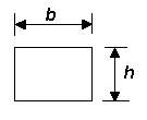
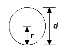
All the equations given below contain I, the moment of inertia of a beam, which is a constant determined by the beam's cross-sectional shape and thickness. The moment of inertia is not related to the length or the beam material. Only rectangular and round solid sections are considered here.
Key to deflection diagrams and symbols
|
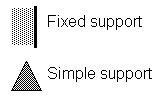
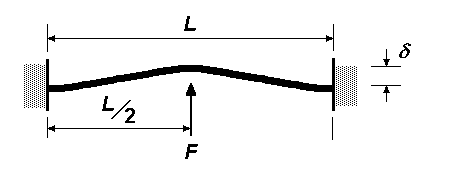
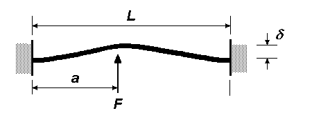
The diagrams show two types of support, fixed and simple. At a fixed support, the beam is held rigidly, and the angular deflection at the point of fixing is zero. At a simple support, the beam can slide on the support and rotate according to the force being applied on the beam. |
L = length of beam
a = intermediate length of beam
δ = deflection of beam
F = force (i.e. the proportion of loco weight being resisted by axlebox)
E = Young's Modulus
I = moment of inertia of beam
Deflection equations and diagrams
Note on diagrams and equations. The diagrams given here have been inverted from their normal textbook presentation, to reflect their application for model locomotive and vehicle axleboxes. However, whilst the equations for deflection have been kept consistent with their textbook presentation, the normal sign convention (+ or –, to indicate deflections in the vertical y axis from the beam datum line) has been ignored, as we are concerned here only with the absolute value of a beam deflection.
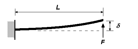
| End load on cantilever beam with single fixed support
δ = FL3 ∕ 3EI This equation should also be used for the deflection of an equalising beam rotating about a fixed axis and bearing onto two hornblocks either side of the pivoting axis. |
 |
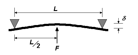
| Centre load on beam with two simple supports (application examples of this configuration) δ = FL3 ∕ 48EI |
 |
| Intermediate load on beam with two simple supports (application examples of this configuration) The deflection at distance a from the left-hand support is: δ = Fa2(L – a)2 ∕ 3EIL |
 |
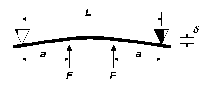
| Twin loads on beam with two simple supports (application examples of this configuration) The application of this would be for two hornblocks pressing up against a single beam. The deflection at distance a from the adjacent support is: δ = Fa2(3L – 4a) ∕ 6EI |
 |
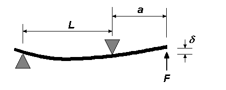
| Overhanging load on beam constrained by two simple supports
δ = Fa2(L + a) ∕ 3EI |
 |
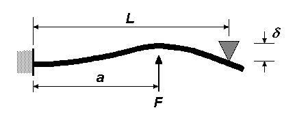
| Intermediate/centre load on beam with one fixed and one simple support
The deflection at length a from the fixed support is: δ = Fa3(L – a)2(4L – a) ∕ 12EIL3 For a load in the centre of the beam, substituting a = L ∕ 2 in the above equation, the deflection is: δ = 3.5FL3 ∕ 384EI |
 |
| Centre load on beam with two fixed supports
δ = FL3 ∕ 192EI With the load at the centre, the deflection at distance a from the fixed support (where a is less than or equal to L ∕ 2) is: δ = Fa2(3L – 4a) ∕ 48EI |
 |
| Intermediate load on beam with two fixed supports
The deflection at distance a from the fixed support is: δ = 2Fa3(L – a)2 ∕ 3EI(2a + L)2 |
 |
Values of Young's Modulus, E
| Beryllium copper | 124 GPa 1 |
| Brass, 70/30 hard temper | 117.2 GPa |
| Brass, unspecified | 96 to 110 GPa |
| Nickel-silver | 132.5 GPa (127 GPa 1) |
| Phosphor-bronze, 5%, hard | 131.8 GPa |
| Phosphor-bronze (92%Cu/8%Sn, or 'CuSn8') | 111 GPa 1 |
| Steel, mild or tool | 212 GPa |
| Steel, mild, low carbon | 210 GPa |
| Steel, mild (hardened) | 201.4 GPa |
| Steel, stainless | 215.2 GPa (190 GPa 1) |
| Steel, tool (hardened) | 203.2 GPa |
It should be noted that these are theoretical values.
A typical value for steel guitar string can be taken as 205 GPa.
There are differences for the values quoted for phosphor-bronze: it would seem that these will depend on whether the material is of the 'spring temper' or the 'extra spring temper' type of 92%Cu/8%Sn phosphor bronze commonly used in snap-over switches.
1 Shigley, Mechanical Engineering Design, 1980, McGraw Hill
Notes on units and dimensions
1 Pa = 1 N·m-2 = 10-6 N·mm-2 = 10-6 kg·m·s-2·mm-2 = 1 g·mm-1·s-2
To obtain force F in the above equations, mass should be multiplied by the gravitational constant g (9.81 m·s-2, or more conveniently for us, 9810 mm·s-2)
The dimensions of Young's Modulus E are ML-1T-2
The dimensions of force F are L2ML-1T-2 = MLT-2
The dimensions of the moment of inertia I are L4
© Russ Elliott
first published 19 April 2000;
slight editorial revision August 2001;
equation for intermediate load on beam with two fixed supports corrected, and deflection equation for the intermediate/centre load on beam with one fixed and one simple support re-expressed, January 2005;
diagram for overhanging load on beam constrained by two simple supports revised, 8 October 2009;
equation for intermediate load on beam with two fixed supports corrected, 30 December 2010
| Return to top of page | Beam menu page | Safety, privacy and cookies |
