
Coal tippler construction detailsby Peter Wilson 1.6M avi videoclip of the tippler operating (More pictures of the coal tippler can be found here.) |
|
It all started rather badly. I had joined the MRC after many years of being a member of the Meccano fraternity. I'd been greeted very well at MRC by the then chairman, Mr Alec Swain; a thorough gent, but I had been totally ignored by the person in charge of Copenhagen Fields, when I asked to participate in the project itself. He was more interested in his beer, as I recall, than seeing if I had anything to contribute.
I later signed up for the Scalefour Society; Prem phoned me two days later to invite me along. This time, I just had time to get my coat off before I was put to work on the layout!
There I was happily cutting little plastic chairs in half and sticking them on to the sleepers, when I came to this four-inch gap in the rail. Having an inquiring sort of mind I asked why there was a hole through the baseboard. I mean you could drive a train down that hole. That's for the 'Tippler' was the reply. I'd never heard of a tippler in connection with a railway, so I thought it must be something to do with an inebriate stationmaster.
The proper meaning was explained and Tony Wilkins produced a photo and told me how coal wagons were to be emptied at Green Street. After studying the photo and making some sketches, I had figured out, approximately, how the thing worked. The next thing I knew I had 'volunteered' to make it.
Tipplers come in various shapes and sizes. There is a good article in Railway Bylines Volume 4 Issue 4 by Adrian Booth on narrow gauge wagon tipplers. The basic idea is quite simple – a section of rail, a little longer than a wagon measured over the buffers, is cut from the track and fixed to a platform. A loaded wagon is shunted on to the platform, which is then rotated until the wagonload falls down a chute below the inverted wagon. Usually, the coal is then lifted by conveyor to a store where it can be used for whatever purpose is needed. The platform then returns to the starting position and the empty wagon is pushed of the platform. This sequence is repeated until the complete train has been emptied.
I cannot emphasise enough the need for good planning, preferably before the baseboard is started. Below the baseboard to one side of the hole was the baseboard side panel. Running across, with about one inch to spare, was a diagonal baseboard strut. Into this V-shaped space I had to cram a motor and gearbox, a small electronic control panel, a chute for the coal, and something to collect the coal from fifty or sixty 16T wagons! It got even worse when we came to the ground signals, but that's another story. All I had was a hole in the baseboard, a photograph and a wealth of ignorance. I assumed that the 16T mineral wagons were all that we would be using, and everyone else assumed that I knew about twenty tonners. Wrong.
Although there is at least two millimetres clearance, shunting a twenty-ton wagon on to the Green Street tippler is not easy. Something that must be explained, especially for those who have never considered it, are the movements involved in tipping coal wagons. The sequence is:
- The wagon is shunted back onto the platform and the train is pulled forward to clear the platform.
- The platform, together with its full wagon is then rotated until all the coal falls out. We have not measured it, but the angle of rotation needs to be more than one hundred degrees.
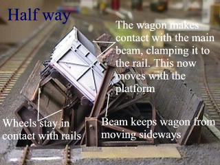
- During these movements the wagon must stay on the rails.
- The train shunts back again, pushing the empty wagon off the tippler.
- It then pulls forward and leaves the second wagon on the platform.
The problems arise when we try to model all these movements. At first I thought that Alex Jackson couplers would take care of everything. In fact I put a very small permanent magnet inside a box on the lower side of the platform and it activates the AJs very well. But the logic is flawed. The first movement is fine. The train pushes back and the last wagon is uncoupled by the magnet. The train pulls forward and the tippler does its thing. However, when the train returns to push the now empty wagon off the platform, the wagon re-couples to the train. Such is the nature of AJs. At first it seems that a second magnet, just past the platform, would solve the problem by uncoupling the first wagon again. It will, but, by this time the second wagon, which has fully crossed the platform, has uncoupled itself whilst passing over the first magnet. It cannot now be pulled back to the centre of the platform.
If one could put electromagnets onto the platform it would solve the problem, but of course you cannot. To be honest I do not know what the answer is. For now we are using 3-link couplings, but it is a bit of a pain by the end of a long running session. If anyone has any ideas on the subject, I will welcome them.
The tippler can be divided into five discrete parts:
- Base
- Platform
- Beam
- Driving mechanism
- Chute base
Base
The base is made from sheet brass and milled sections. I made a frame, right-angled in section, which is a push fit in the hole in the baseboard. The vertical component of the frame is deep enough to cover the thickness of the baseboard timber. On the horizontal components, at each end, is a bracketed post for the main pivots. To the rear of the base is fixed an angled sheet, lined with double thickness second hand sleepers. This guides t'coal into t'hole.
Platform
In its normal position the platform sits just below the ballast so that the rails are level with the fixed rails on either side. At its outer side, the platform is pivoted to a girder structure, and on its inner side it rests on the base. The girder structure passes backwards and upwards through the main pivot point. About halfway up the vertical parts of the girders is a beam, which is free to swivel. Above and behind the pivot point, the girders, on either side, curve to form two quadrants, which are braced to the vertical parts. There is also some horizontal bracing between the side components. The quadrants are of U section in the cavity of which sit a chain. The chains are fixed to the girders at the top and pass down through the chute to a capstan below. I made the platform of thin brass sheet, heavily embossed with rivets, and printed circuit board, forming a sandwich. As the rails carry current, the two halves of the top are separate and carry the rails. The rest of the platform structure uses various sizes of milled brass section and is best seen in the photographs. The chain is something that I used to make for a living and is of silver.
Electrical connections are made to the two upper halves of the platform and the wires pass down through the front of the chute. The beam, which is hinged to the vertical girders, is to steady the wagon during the tippling process. It is not to be confused with the main beam, which will be described next.
Beam
The beam has the function of clamping the wagon to the rails during the tipping sequence. A massive beam, probably 9" by 18" in section, is fixed to a girder structure. The girder structure has heavy weights fixed to it below ground level and the complete assembly is free to rotate on the same pivot pins as the platform. Milled brass sections were used to make the beam and girder construct, with lead for the weights. The verticals are pivoted on the outside of the platform supports. All the parts were riveted to give the impression of great strength.
Motor and gearbox
A Tenshodo motor with a gearbox drives the capstan, and some electrical circuitry enables the speed to be varied from real time to exhibition time. The reason is that at the correct normal speed, not a lot of movement is seen, and the viewers will find their attention span under threat. I think the gearbox gives about 80:1 reduction, but, as mentioned before, the speed is set electrically. There are three speed settings. Tony Wilkins did the electrical work, thank the Lord. Micro-switches control the limit of movement in each direction, with a slight over run on the way down to ensure that the track is lined up. The capstan was made from Meccano parts.
Chute
A pyramid-shaped chute was made from some tin boxes and fixed permanently to the underside of the baseboard. The screw-top lid of a jar was soldered to the lower end of the chute. A plastic jar, big enough for about sixteen hundred tons of coal, screws onto the lid, and can be quickly changed when full. The lifting chains pass down through the front of the chute and wrap round a capstan fixed outside the chute.
Assembly
The frame, chute, motor and gearbox were fixed to the underside of the baseboard, and the main parts, the platform and the beam to the frame. The wires for the track power and the driving chains were fed through the front of the chute and attached to the motor and capstan. Power was connected and tested.
Action
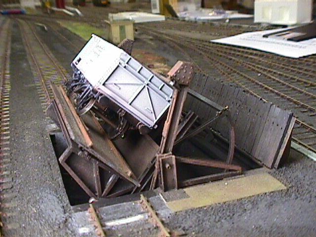
A loaded wagon is shunted on to the platform, just clearing the small hinged beam. The train is then withdrawn. The motor is switched on and drives the capstan, winding in the chain. This causes the girder and platform assembly to begin rotating around the pivot points. Because the platform was supported on the 'near side' by the base, and on the 'off side' by the hinge; as it lifts, it will tilt sideways, causing the wagon to come into contact with the first beam. This small contact is enough to steady and brake the wagon in place. When the assembly has moved about fifty degrees, the top of the wagon comes into contact with the main beam. The resistance to movement caused by the weights attached to the beam, cause the beam to clamp the wagon to the rail, but, as the beam is pivoted about the same axis as the platform, it now turns with the wagon, while maintaining the pressure. This pressure holds the wagon to the rail throughout the movement. At this point the capstan is lifting the whole assembly and the wagon! After a movement of about one hundred degrees, the load has tipped out of the wagon and the tippler is returned to the down position. The empty wagon is now shunted off the platform.
© Peter Wilson
September 1999
| Return to top of page | Green Street menu page | Safety, privacy and cookies |