The High Level Models Pannier chassis kit, intended to go under the Bachmann body, is designed to be built with either rigid axles or using the supplied compensation beams (on the centre and rear axles, with a rocking front axle). This article describes an alternative suspension – the fitting of a CSB.
Fitting a CSB to a High Level Models Pannier chassis
by Mike Smith
pictures by Mike Smith, James Moorhouse and Russ Elliott
This article is a slightly expanded version of the one first appearing in Scalefour News 182, and includes some additional pictures of James Moorhouse's CSB Pannier.
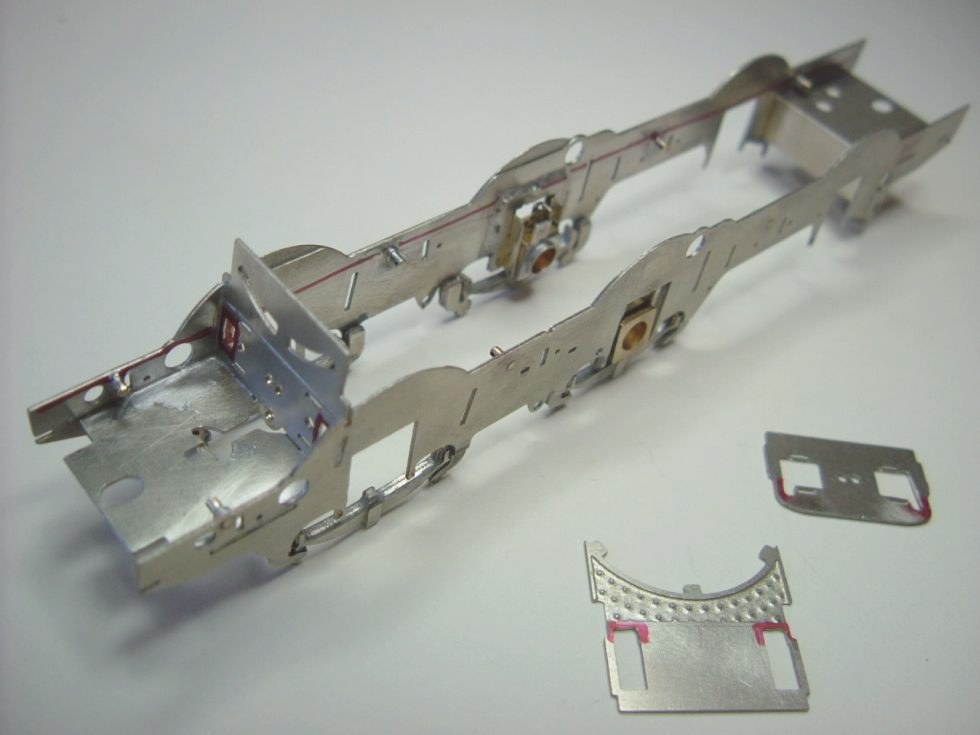
Preparing the frame and the spacers for the CSB
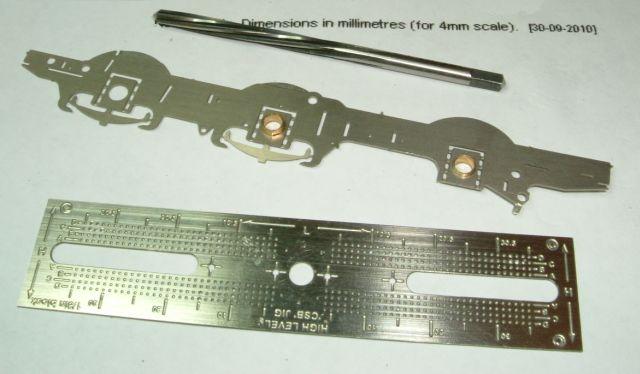
The chosen fulcrum plot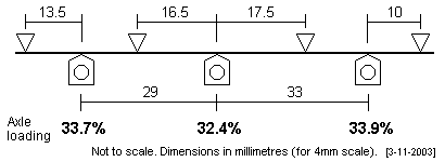 was marked on the mainframe, with the rigid axle holes etch parts intact, using line 'C' of the High Level Models CSB jig. Line 'C' of the CSB jig was chosen, as this seemed the easiest, but line 'B' is an alternative viable option.
The centre axle hole is the starting point when using the CSB jig. You may have to open out the centre hole in the jig slightly to accept the axle bearing supplied with the jig. All the axle holes in the frames will need to be opened very slightly to accept the bushes so as to fit the jig, but not too much because you are looking for an interference fit. The outer axle bushes will need two sides filed flat to fit the outer slots in the jig (or very lightly wipe the sides of the slots in the jig with a file). Each fulcrum point was drilled 0.5mm using a hand drill. After drilling, a line was marked, using the holes as a horizontal datum, down the full length of the chassis, to determine where to make the enlarged apertures in the chassis cross members.
![]()
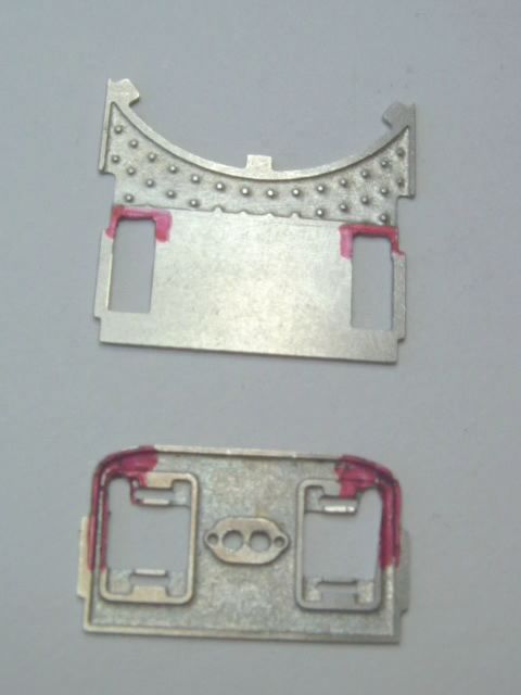
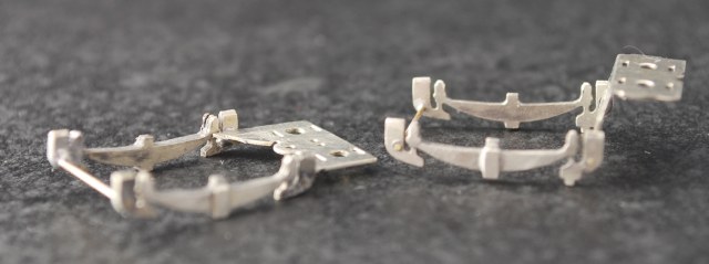
The diagram above shows the apertures needed to be cut in three of the frame spacers to clear the beam. (The rear frame spacer requires no modification.)
The front spacer (kit part No 4) had a slot measuring 1.5 x 2.5mm hard against the frames. The motion bracket spacer (No 5) is a little more tricky, and a very small diameter round file was used to file out the top outside (inner) corner on bothsides, followed by filing down the outside (inner) sides with a flat file to allow for the up and down play of the beam. The firebox (middle) spacer No 6 is almost ready as supplied, and only about 2mm more from the top of the compensation beam slots, just short, say 1mm, from the firebox bottom, is required.
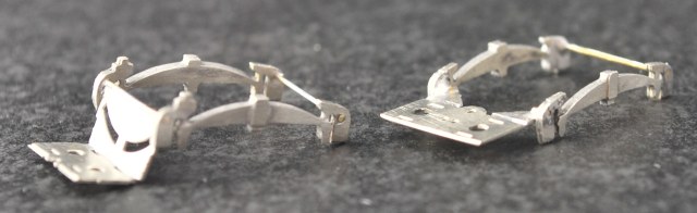
The picture adjacent shows two of the frame spacers (the middle spacer and the motionplate spacer) with their beam clearance apertures, prior to being fixed into the frame.
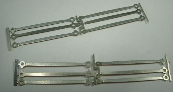
The High Level rod etches
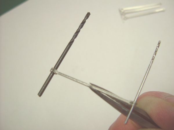
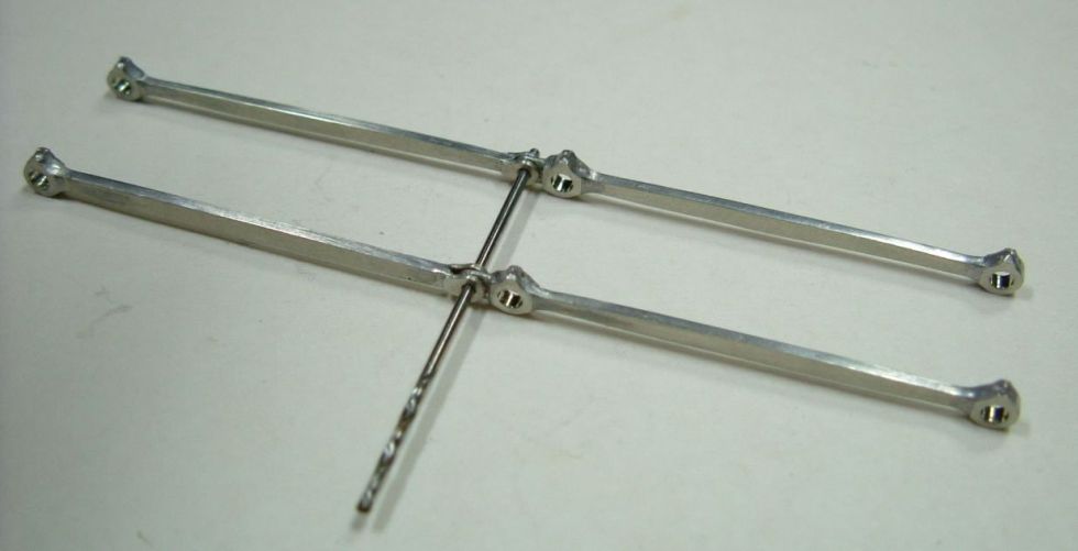
Laminating the rod etches together, with drills for alignment. The nearer hole is for the forked knuckle. Before laminating the coupling rods together the etches were drilled them out individually with a 0.8mm (for the knuckle joint) and 1.4mm (for the crankpin holes) with a small electric pillar drill. All the holes were gently countersunk and the rods cleaned up to ensure they went together with no kinks or bumps. These rods are very fragile when removed from the fret so be careful. The drills were used when starting to laminate the rods together, being replaced by cocktail sticks to keep solder from blocking the holes when soldering the ends. Do not be afraid to use plenty of solder.
Finished rods awaiting their knuckle pins. The instructions advise to solder the 0.8mm rivet. I chose to gentle hammer the rivet on my rods with a couple of light taps with a toffee hammer on something hard a small anvil in my case.
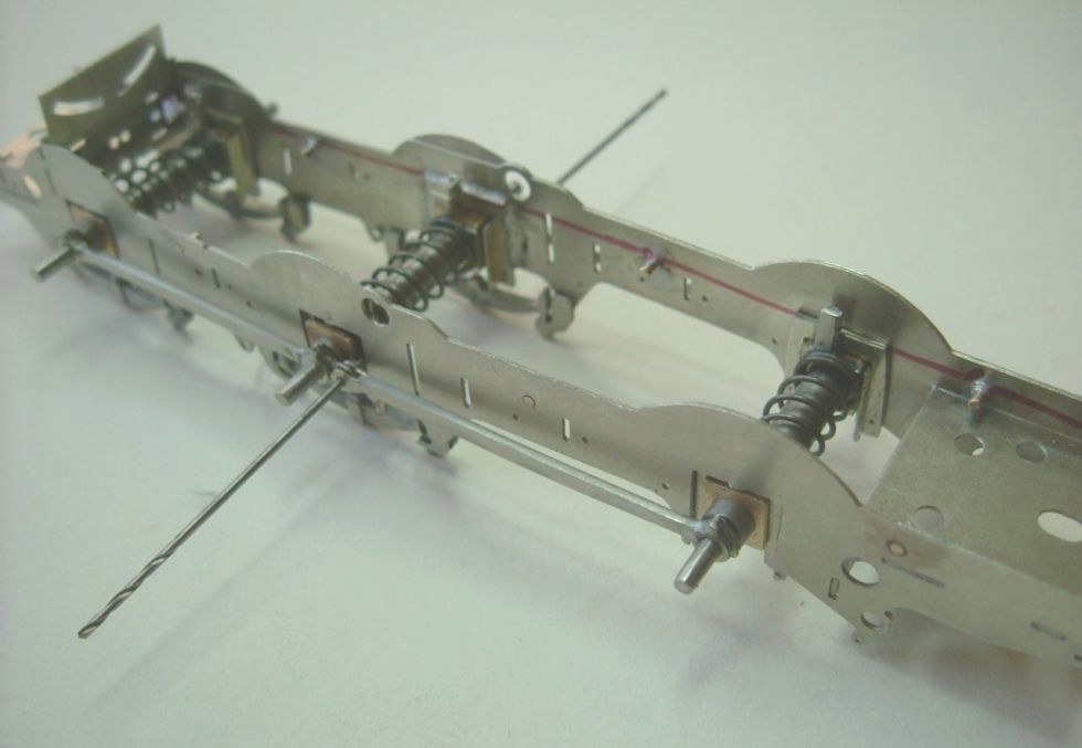
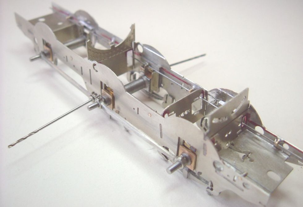
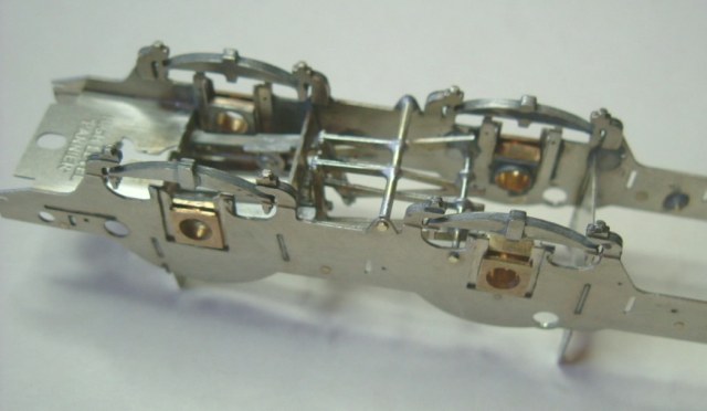
Setting up the frames
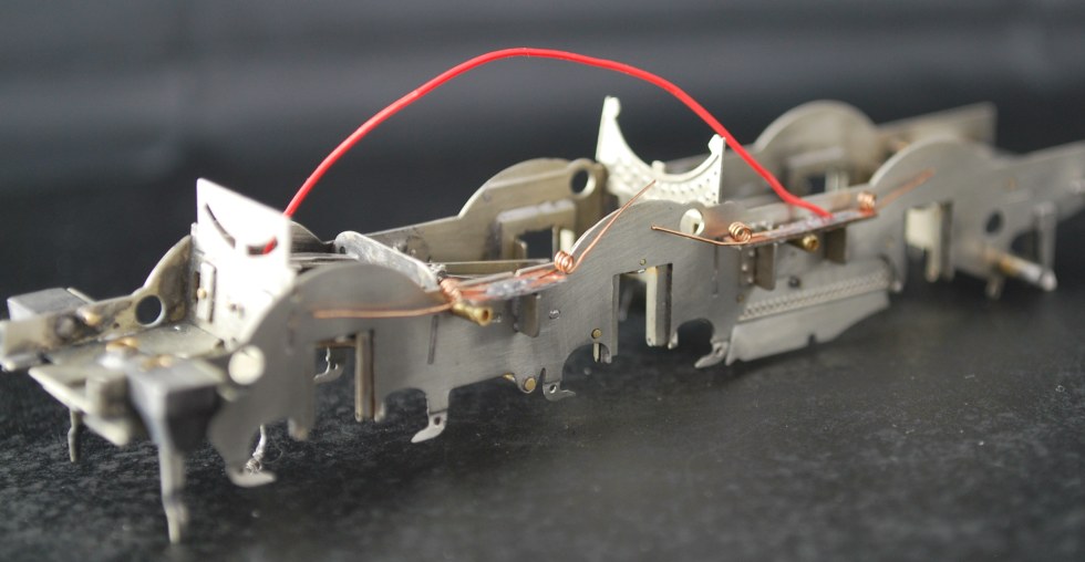
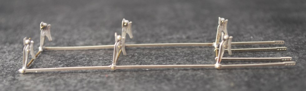
The frames are drilled, together, for their fulcrum points. After separation, and opening up the 0.5mm fulcrum frame holes to 0.75mm, Markits 'WD short austerity' handrail knobs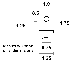 are soldered in, using a short length of wire through all the knobs for good alignment.
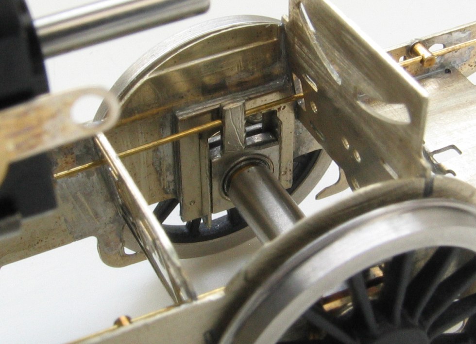
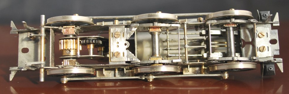
Having fixed the handrail knobs in the frame, frame spacers begin to be added. A pair of standard High Level hornblocks with their CSB carriers has also been added to the centre axle. The carrier tags are soldered to the rear boss of the axle bearings before fitting to the hornguides. The centre axle acts as the reference point when fitting the hornblocks for the front and rear axles. The motion plate and middle spacer clip into place when gently opening out the frames, ready to be soldered in.
Using hornblock alignment jigs, and 0.8mm drills through the knuckle joints to keep the rods 'square', the front and rear axle hornblocks are positioned and secured.
The front axle hornblocks are High Level's 'spacesaver' variant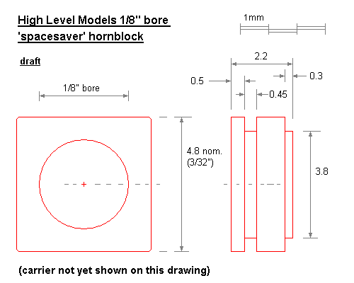 , which are a bit thinner than the standard ones, to clear the inside motion. The rear axle hornblocks are also spacesavers, to cater for gearbox widths. In this particular case however, the gearbox chosen didn't require the spacesavers, and standard High Level hornblocks were eventually used for the rear axle.
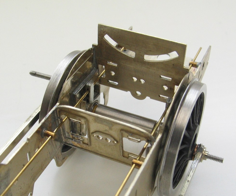
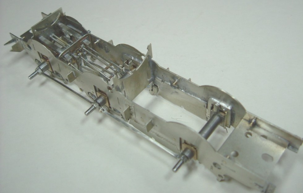
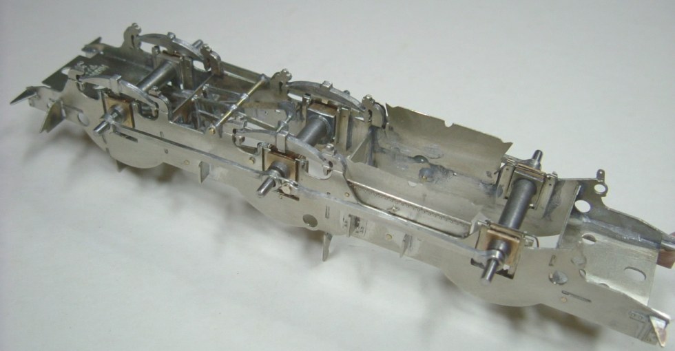
The motionplate and middle spacers are tested to check their apertures clear the beam.
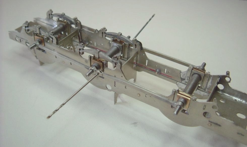
The following two pictures are of James Moorhouse' chassis showing the clearances of the apertures in the frame spacers, with a temporary brass wire for the spring.
Inside motion
The complete inside motion, as per the kit instructions, was fitted.
The slide bars 14/15 are handed O/S & N/S with cutouts at the bottom to allow for the front axle boxes to slide unobstructed in their hornblock guides.
High Level spacesaver axleboxes were used for the front axle, since the standard ones are too tight against the inside motion.
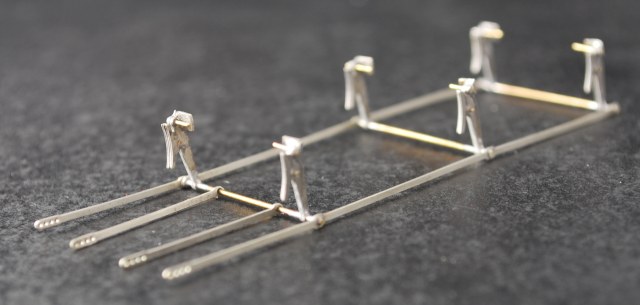
The drop links and radius arms are drilled out by hand in their frets (No 16/19 - 20/21). The holes were gently countersink with a larger drill by hand and cleaned up so they lay perfectly flat together (the same as with the coupling rods). Then, inserting the 0.5mm wire in the front, they were soldered in together with the radius arms sandwiched in between the drop links. When soldering the drop links and radius arms together it is best to use a minimum amount of solder, to bring out all the detail in the links and arms, including filing the 0.5mm wire square and evenly to represent nuts and bolts etc.
The connecting rods fit in the locating holes marked 'C'. The slidebars had to be gently prised open to allow the connecting rods to fit.
The vacuum pump assembly was fitted as per the kit instructions.
The protruding wire from the pump had to be filed as it obstructed the suspension wire at the height I was using. (Using the 'B' height setting of the CSB jig would probably not allow the pump to be fitted.)
The pump inhibits using the top centre brake hanger wire from using the 0.5mm hole, which I found out to my detriment when fitting the brakes. It is possible to fit the pump but I decided to remove it.
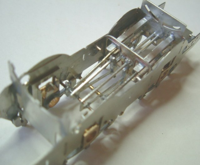
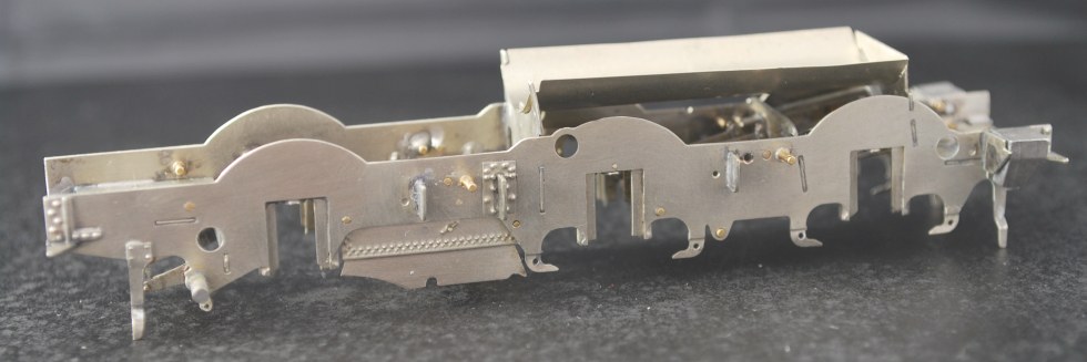
The following two pictures show the frame spacers and inside motion fitted in place, and frame brackets being added to the outsides of the frames. The knuckle pins on the rods are also fitted, which were later popped with a 0.4mm drill to give a better representation of the coupling rod bolt hole.
Revising the springs
The previously soldered springs were detached, and made into separate 'screw-on' assemblies, which allowed the hornblocks to be dropped from the frames.
The spring attachment plates were made from the redundant OO frame spacers in the kit.
The front spring plate was attached to the front spacer, and the middle spring plate was attached to a new gash frame spacer soldered between the frames. The second picture is a closeup of the gearbox clearance on James Moorhouse' chassis.
.jpg)
The tale of the pickups
The picture adjacent was taken before the springs were made detachable on separate subassemblies, the initial pickups being 'curly-wurlies' of 0.33mm phosphor bronze fixed to gapped-paxolin pads attached to the underside of the frames. The ends of the pickups bear against the wheel flanges.
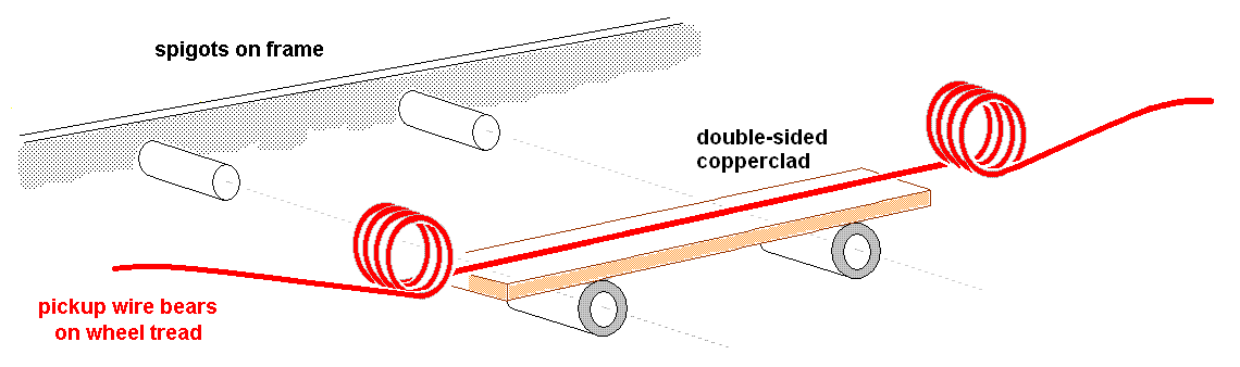
To facilitate the dropping out of the axles and their hornblocks from the frames, the springs were de-mounted from the frames, and made detachable, as illustrated below. The earlier underchassis curly-wurly pickups were replaced by top-wiper curly-wurlies. These are also mounted on paxolin strips on the underside of which are 1.6mm brass tubes, which slide onto 0.9mm spigots fixed into the sideframes and positioned so that the underside of the paxolin strips are level with the top of the frame sidebrackets. The spigots and tubes allow the paxolin strips to be taken off easily so that the pickup pressure can be tweaked. The pickups are shaped to go under the body splashers.
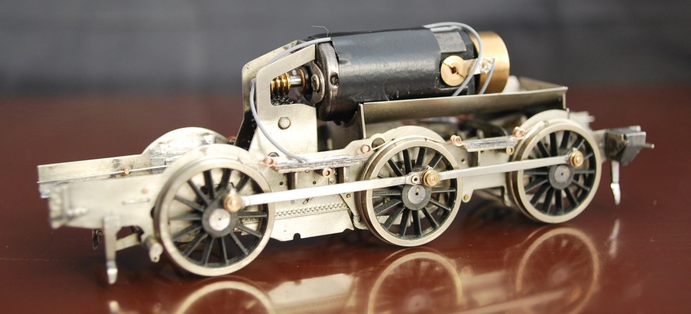
The boiler underside in position, and lower, the motor fitted. The body prevents the motor from rotating, so the motor didn't really need its own torque reaction arm.
Brakes
The instructions' diagram fig 1 shows the steam brake cylinder fitted to the O/S front hole, but it should be fitted to O/S rear hole as in fig 6/7. Beware the steam and hand brake lever assemblies are sided and the steam lever is incorrectly numbered 45/46 instead of 48/49. Chris Gibbon of High Level informs me all later instructions have been revised.
Chris Gibbon recommends the rear inner brake pull rods (No 65) should be soldered to the firebox sides after fitting. I decided to glue at the final fitting stage.
The pickups are hidden from view with the body on the chassis.
.jpg)
Test running, prior to brake fitting, on the North London Group test track, in August 2012. The loco has yet to be weight-balanced. Including the approx 33g of cast weight in the bunker, the loco and its chassis is currently a total of 160g, and is running on 0.012" beams. Extra weight needs to be added to the front end of the loco to bring the loco into balance and up to nearer a 180g to 200g total weight, for which 0.013" beams will be more appropriate.
© Mike Smith, James Moorhouse, Russ Elliott
15 December 2013
| Return to top of page | Safety, privacy and cookies |