Low profile motor units
by Ted Scannell
|
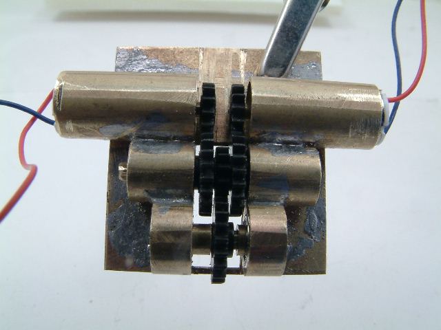
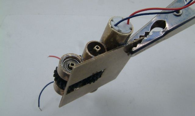
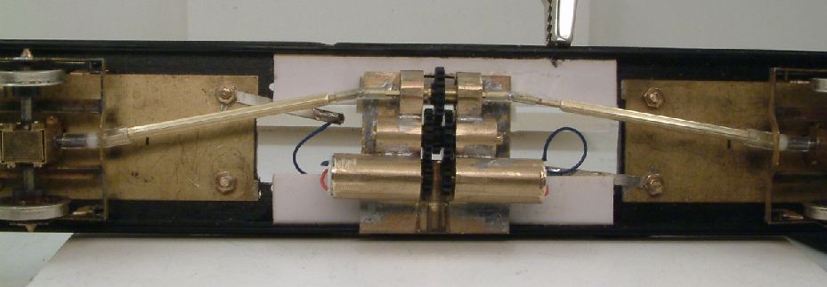
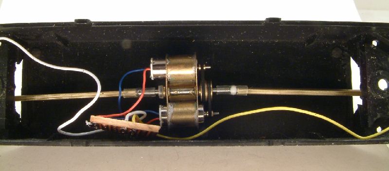
Double-motor single-stage reduction unit
These prototypes use Nigel Lawton 6V 6mm diameter micromotors, and 0.4 Mod gears courtesy of Chris Gibbon of High Level Models. The ballrace bearings on the main shaft are 5mm x 2.2mm x 2mm bore, but flanged types may be substituted at the tube ends and fixed with a bearing fit. All the brass tubes are standard stock. The first unit shown here is a 2-motor arrangement with single-stage gear reduction. It is a development of a previous micromotor arrangement. The motors are wired in series. It may prove useful to anyone with a vertically challenged model, such as a tram, where it is desirable to drive both bogies, though driving from both ends is not mandatory. The drive shaft tube can be shortened to the length of the motors plus gears, about 16mm. If even more torque is desired, two more motors could be fitted to the other end of the drive shaft tube. 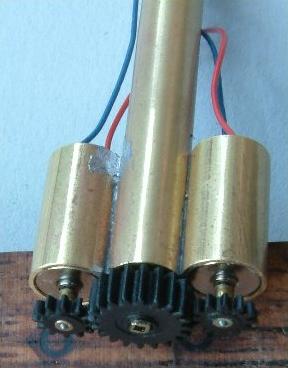
|
   Subsequent to these pictures of the assembled unit being taken, the 12t gears were offset (as shown on the diagram) so they don't both wear the same place on the 20t gear.
|
|
Single-motor double-stage reduction unit
Here is a sketch of a single-motor double-stage gear reduction unit. |
 |
|
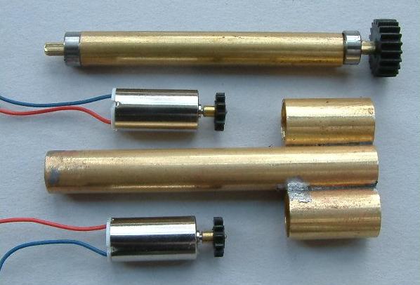
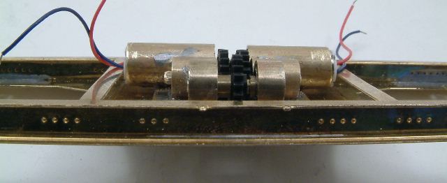
Double-motor double-stage gear reduction unit
The two stages of the 12t and 20t gears give a reduction of 2.78:1. Coupled to Bill's 14:1 gearboxes, this is an overall reduction of around 39:1. The motor tubes are 7mm od, the intermediate are 6mm od, and the final output tubes are 6mm sleeved with 7mm, to hold the ballraces but maintain the gear mesh distance of 6.5mm. The intermediate and final gears are mounted on square section brass tubes running in 5mm x 2mm ball races. Constructionally, the tubes are soldered next to each other on a piece of brass stock sheet, and the 5mm wide slot cut out after with a razor saw. The intermediate and output shafts are 1/16" square brass tubes, which allow for a nice sliding fit in the ball race bearings and a good tight gear interference fit, though they are easy enough to slide into place. The motors are 34mm from end to end, and the overall width over the tubes is approx 20mm wide. This unit is currently installed under a test MU chassis, although some of the pictures here show the unit in a Judith Edge ES1 chassis. The 150g test MU chassis with two axles powered can comfortably accelerate three additional 150g pinpoint-axled vehicles on the flat, and can pull the three vehicles up a grade of approx 1:130. Top speed for the 4-vehicle unit on the flat with a Pentroller was approx 75smph, which indicates for this type of load the motors are revving at approx 28krpm. |
|
In this MU chassis, the angle of the transmission shafts to the bogies can be reduced by moving the motor unit offcentre.
|
|
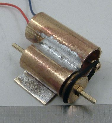 Belt drive
This single motor has a 3.6:1 belt drive reduction, the small pulley (on the motor shaft) and the belt being obtained from Nigel Lawton, and the larger pulley being home made. 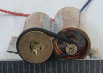
|
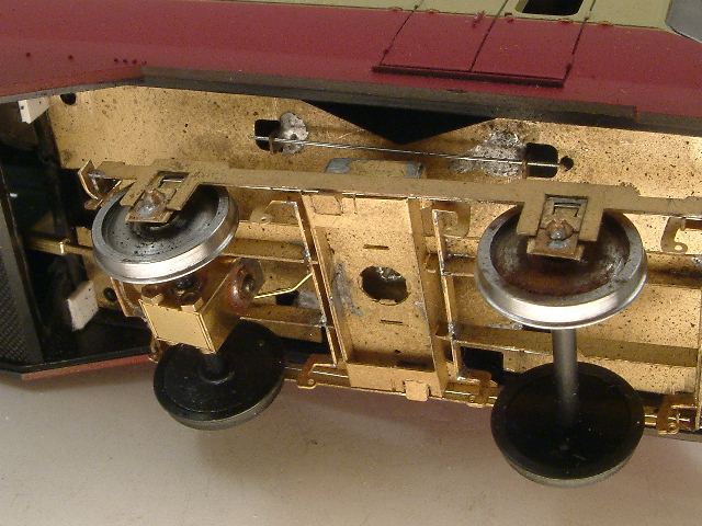
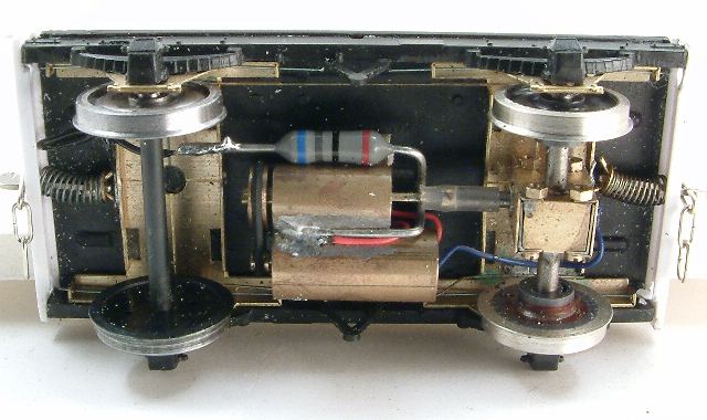 Shunting horse application A single motor with its 3.6:1 belt drive driving onto a 14:1 Bill Bedford gearbox on one axle, giving an overall reduction of approximately 50:1. Wheels are 3' diameter (Ultrascale wheels, one shorted to the axle, the other axle has one Alan Gibson all-steel wheel, and a plastic centred version on the other side) running in standard Bill Bedford sprung wagon W-irons mounted in a 9' wheelbase plastic chassis kit. The pickups on the insulated wheels are 30SWG phosphor-bronze wire.
The running resistance of these motors is in the region of 80Ω, and a 0.5W-rated resistor of equal value is in series to keep the potential difference across the motor to approximately 6V. The optimum overall weight for the wagon seemed to be between 40g and 50g. This provided enough traction to haul 4 loaded mineral wagons (a total of approx 170g) up a 1:130 gradient. Weighting the wagon to significantly more than 50g increased the traction, but the motor ran too hot when pulling a larger load. Top speed of the loaded wagon without additional drawbar load is approximately 55smph, at which speed the motor armature is developing approx 27krpm. |
|
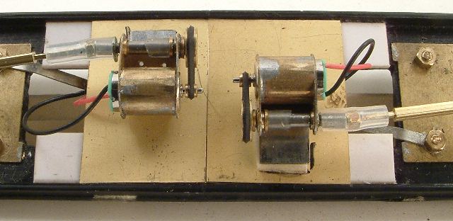
MU application with belt drives
This MU test chassis has two independent 3.6:1 beltdrive reduction units, using Nigel Lawton 6V 6mm diameter micromotors and Bill Bedford etches, driving onto the inner axle of each bogie via silicone tubing and ball UJs and telescopic cardans. The motors are temporarily hung on double-sided foam tape and styrene, for a quick test, but they could be tucked up approximately 3mm higher in between the solebars of this DC Kits chassis if fitted directly to the floor. The motors are wired in series. The unit starts moving at about 55mA and trundles along nicely at 58-62mA. Under load, and with 14V applied across the two motors, the unit draws 83mA. |
|
|
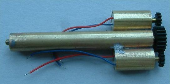
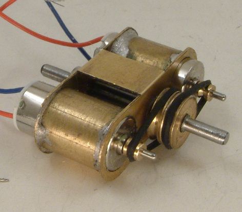
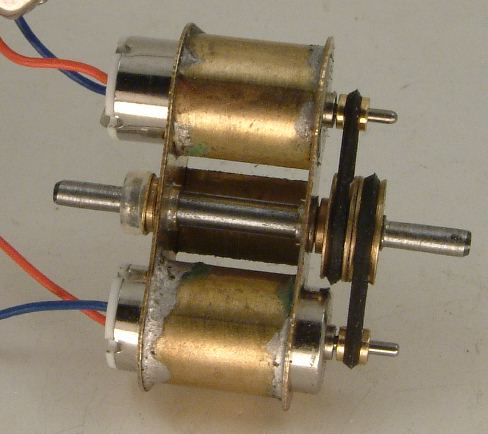
This is a double motor unit with 3.6:1 belt drive primary reduction stage. An advantage of this arrangement is that the belt tensions offset on the common shaft, so there is minimal sideloading of the common shaft against its bearings. It could be made slightly more compact by using 10mm long motors rather than the 12mm long ones shown here.
Nigel Cliffe has been experimenting with a similar two-motor arrangement in 2mm scale. |
|
|
|
|
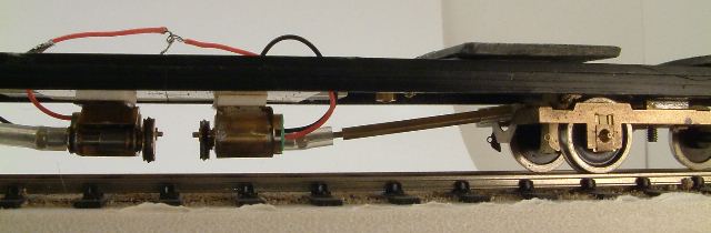
 A double motor unit with 3.6:1 belt drive primary reduction stage mounted in a Lima (now Hornby) GWR Railcar underframe.
Each bogie has a single 14:1 gearbox on the inner axle. The primary springs are 9 thou. Each secondary has a springrate of approx 1.4N/mm, comprising a 15 thou spring over a 22.5mm span with a bolster width of 9mm impinging against the spring. One side of each wheelset is live to the bogie frame. Current is picked up via the secondary springs. The bogie plate is a Bill Bedford etch. The American pickup system (one side, i.e. two wheel treads, per bogie) is not wholly reliable for a single-car application, particularly for a lightweight unit such as this (the unit is currently 94g, and is likely to be weighted up to approximately 140g). The American system becomes sufficiently reliable in an MU traction-bus application. |
© Ted Scannell
4 December 2006
updated 7 May 2007
updated 25 May 2007
updated 19 September 2007 to correct stated gear ratios on beltdrives
updated 29 October to include MU belt drive application
updated 1 December 2007 to add double motor etch arrangement
updated 7 December 2007 to add GWR railcar
| Return to top of page | Safety, privacy and cookies |