D/EMU spinepictures by Ted Scannell |
This selection of pictures of Ted Scannell's 3-car DMU is based on a pre-production version of a D/EMU spine kit from Bill Bedford. It is expected the production versions of the kits will differ slightly from those illustrated here.
A Hornby class 110 DMU was used as the testbed for these components. |
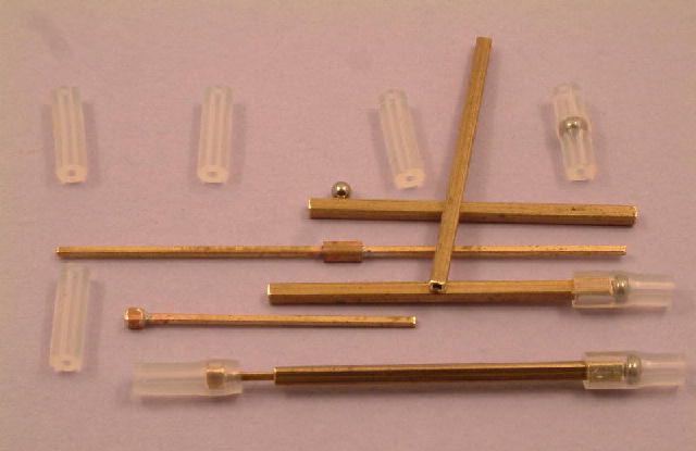
| The transmission components. The telescopic cardans are 0.8mm (1/32") square section sliding in matching thin-wall brass section, with silicone tubing and ball UJs, assembled as per construction notes (also available as a pdf). |
|
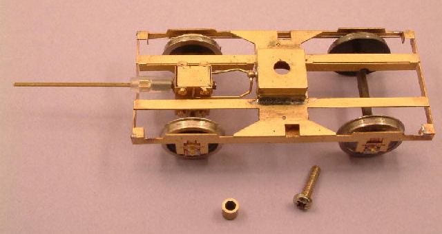
| A bogie plate, viewed from the underside. The handrails knobs for the secondary springs are Markits 'original' 1.5mm diameter handrail knobs. It is expected that the production version of the kit will feature foldup tabs to hold the secondary springs. |
|
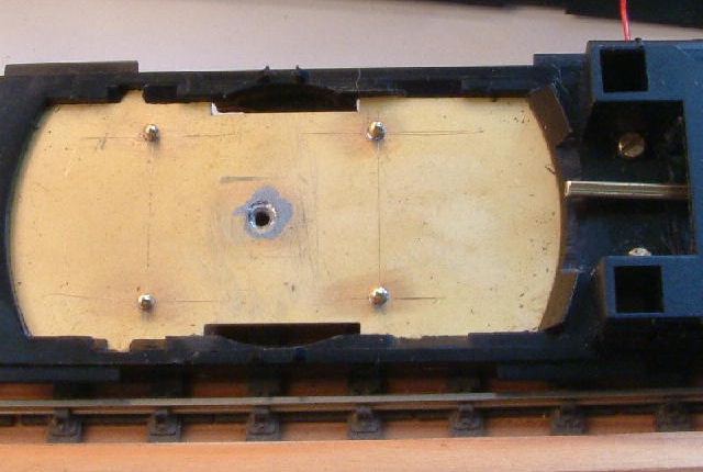
| A bogie plate in the DMU chassis viewed from the top. The bogie plate fits into the chassis from the top. The soldered nut is for the bogie pin. |
|
|
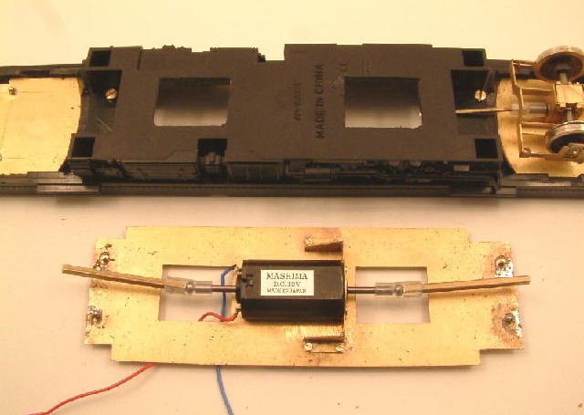
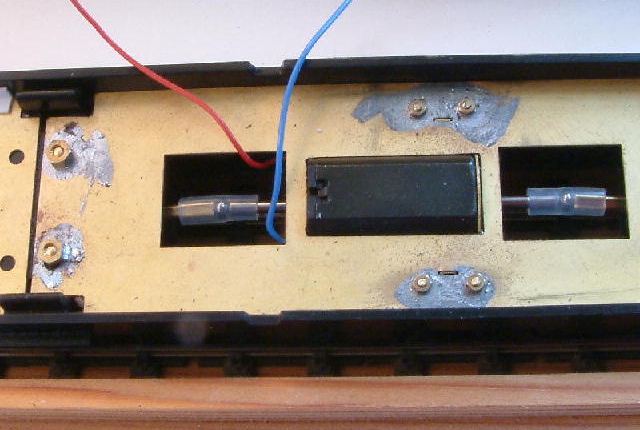
Underside view of the centre portion of the Hornby 110 chassis and the motor plate, which is fitted into the chassis from the top.
The motor is a Mashima MHK1020. |
|
| Topside view of the motor plate, to which its chassis securing nuts are soldered. The motor plate is electrically separate from the adjacent bogie plates, to facilitate the 'American' system of pickup. The top of a Mashima 1020 motor sits slightly proud of the top of the motor plate. |
|
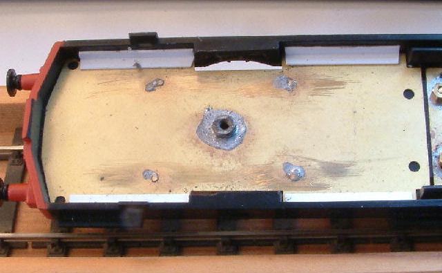
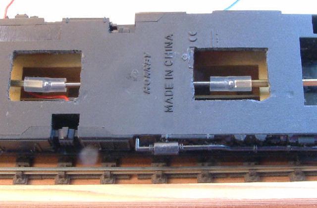
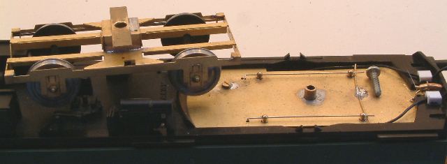
| Underside view of the centre portion of the Hornby chassis, with initial apertures hacked for eventual flywheel/ATC accomodation. These apertures were later extended to allow the fitting of flywheels/ATCs on the motor shaft. |
|
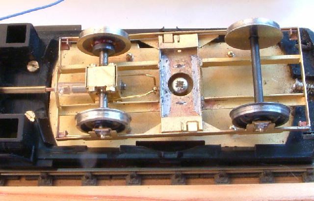
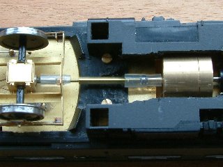
| Topside view of an assembled drive bogie. The secondary bolster box in the production version of the kits is wider than shown here. The bogie bolt is M3, with the small 3mm i.d. collar allowing the bogie free rotation and vertical movement on the secondary springs. |
|
| Underside view of an assembled drive bogie, showing the large clearance hole for the bogie bolt. The bolt is nipped up to the collar, the bolt's head diameter retaining the bogie. |
|
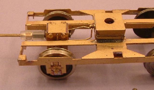
| Closer view of an assembled drive bogie, showing the torque reaction link between the 14:1 Bill Bedford gearbox and the bogie. The torque reaction link is held in a 1.5mm diameter Markits handrail knob fitted to the bogie's top bolster box, and the two ends of the torque reaction link clip into holes in the top of the sides of the gearbox. |
|
| End view of an assembled drive bogie. Adoption of the American pickup system throughout the 3-car set allow wheels to be cleaned less often than conventional drive bogie pickup systems. |

|
| A drive bogie in the DMU chassis. (This picture was taken before the secondary springs were fitted.) |
|
|
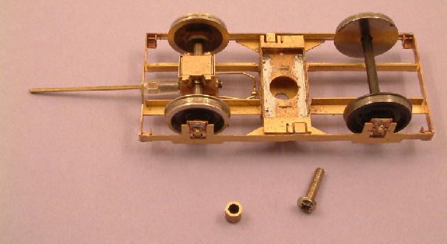
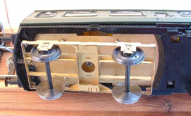
Underside view of one of the non-driven bogies. One tyre of each wheelset on each bogie is a standard insulated one, the other being all-steel*, and therefore shorted to its axle. The electrical path to the motor from each bogie is via the axle pinpoints to the bogie frame and through the steel secondary springs to the bogie plate. No tyre pickups are involved. (This picture was taken before the secondary springs were fitted.)
* available by special order from Alan Gibson |
|
| View showing the secondary springs fitted through the handrail knobs on the chassis plate. One end of each spring is bent over at a right angle, and fits into a hole in the bogie plate. These bends and holes prevent the spring from sliding out when the unit is in service, but the hole size is such as to allow the spring to deflect freely as intended. |
|
|
End view of the 3-car set, with the driving motor car in the foreground. At this stage, Modeltorque 13mm ATCs had been fitted either side of the motor (see below), requiring a complete hackout of the underside of the centre portion of the Hornby chassis.
Power to the motor is bussed throughout the whole 3-car set, but the details of that implementation will have to await another story... 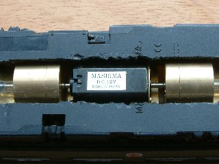
|

|
© Ted Scannell and Russ Elliott
September 2005
| Return to top of page | Safety, privacy and cookies |