This is a republication of Graham Hickson's original page, which was lost when Virgin Media withdrew its customer webspace facilities.
Axle-hung traction motor
by Graham Hickson
Introduction
I'm modelling BR 3rd rail electrics in P4, my chosen period is around the time of the Bournemouth electrification. I was never happy with the old 'pancake' type motor bogies and a big motor inside the coach was even less appealing. What I wanted was to get away from the worm drive and the motor shaft at 90° to the axle. I also wanted the same number of motors per unit as the prototype, i.e. 2-car unit 2 motors, 4-car unit 4 motors. I first toyed with the idea of using small Mashima motors axle hung but this would be expensive and far too powerful. Two things that helped me down this route – Ted Scannell built an axle hung traction motor using a belt drive. I did some sketches with belt drives but wasn't entirely happy with the arrangement. I wanted to make it more compact. It was browsing the NWSL web site that I found a nose-hung traction motor unit called a 'Magic Carpet' (for 0 scale American street cars). This used a small can motor with a plastic housing and a three-stage gear train. This was what I was looking for.
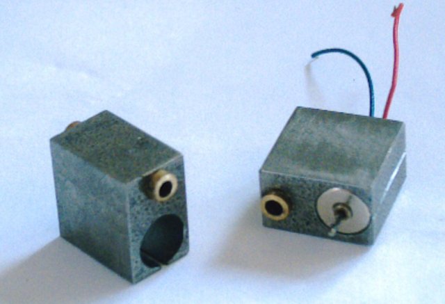
The motor blocks
The original intention was to use cast iron. The reason for this was the motor block would act as a bearing for the axle, and it would act as a heatsink for the motors. An early prototype was made in iron, but all I have available is rough offcuts and there was a lot of work required to get it square and to size. A change to steel was made because it is readily available in sizes that suit the motor block, which is 12.7mm square by 8mm thick. Brass bearings are fitted and protude to fix the wheel back to back. The block on the right has been fitted with motor which is a Nigel Lawton Micro Motor. These motors measure 6.03mm in diameter, so a 6mm hole is too small, and a custom reamer had to be made. This was after the first one was opened out with a file, and the commutator was push out the back of the motor.
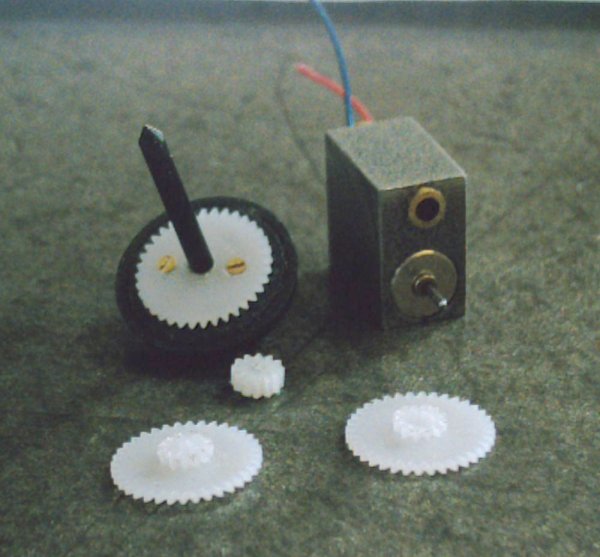
The gears
These gears are made by Didel in Switzerland. The pinion is a 12t and has to be cut in half. The two spur gears are 36/12t, and the 12t has to be reduced in thickness, with one of the bores being opened out to suit suit the axle diameter. The final drive gear is a 36/12t with 12t cut off and secured to an Alan Gibson wheel and pin point axle with 14BA countersunk screws.
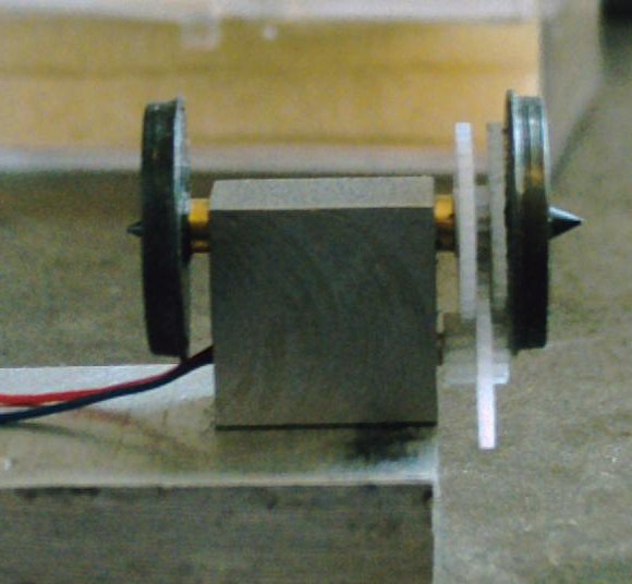
Assembled and ready for testing
The brass bearings are 3mm long to reduce friction. and the clearances are very tight. Too loose and everything wobbles around with the risk of the gears becoming displaced and jamming. The motor shaft is only just clear of the wheel back. Too tight and the motor would be severly overloaded. This view shows the Gibson wheels before the backs were faced flushed.
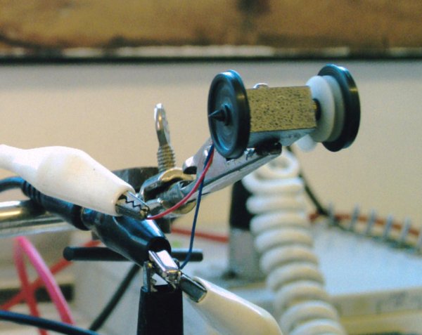
Testing under power
Running at the full 6V before any grease was applied. The second motor was greased on assembly. They were briefly run up to 12V, just to see what happened. They run faster and didn't get much warmer. This testing also gave a bit of running in which reduced the starting voltage. After prolonged running at 6V the motor blocks were just warm, which was very encoraging as it showed that the heat-sinking of the block was working. When I received my first two motors I ran one at 6V and held the motor in my fingers, it got a lot hotter than this set-up.
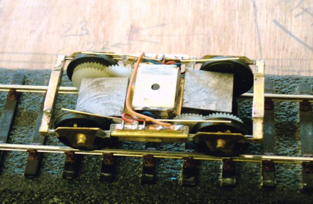
The motor bogie
Two motors assembled in a heavily modified Masokits pinpoint bogie. The motors are wired in series for testing and fitted with temporary pickups. Load testing will use a Bachmann Mk1 using DC power. It is intended to carry out full testing using an Ian Kirk 2-BIL set, DCC and live axle/bogie pick-up. I'm going to try a parallel/series switching arrangement using a function and relay on the DCC.
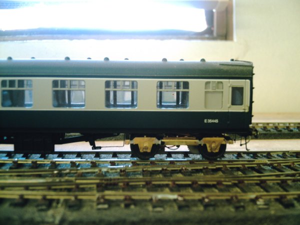
Load test
Under a Bachmann Mk1 for load testing. All my coaches are fitted with Masokits pinpoint bogies so they are a straight swap, hence the temporary pickups. The bogie was quite happy moving this coach and another Bachmann Mk1. Control was very good, with slow running and a reasonable top speed. It was a little noisy but this is possibly because one of the final drive gears is slightly eccentric. A drilling jig will need to be made to correct this. Also it was found that the motor pinion on the same unit wasn't in full engagement with it's spur gear. A minor adjustment to the motor in the block fixed this.
In service
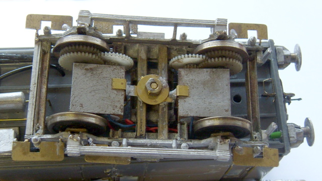
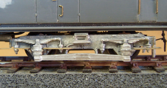
This is a view of the bogie in it's present and probably permanent home, under an Ian Kirk 2-BIL. The pieces of brass at the edges of the blocks are 'C' shaped clips soldered to the bogie frame to prevent the motors from rotating around the axles. This is the only modification to the assembly plus the addition of side frames and details as seen below.
A Zimo MX64 DCC decoder is used with an 8-pin plug made up with parts from Maplins. I can't recommend these decoders highly enough, especially after trying a Lenz Silver "Silent Drive". These work great with my Heljan diesels, but with these coreless motors, it sounded like a bag of spanners. The Zimo has more configuration options than the Lenz, and it did take a little bit of experimenting. Straight out of the box it ran well, but the starting voltage was too high. So a custom speed curve was set-up using JMRI Decoder Pro with my NCE Power Cab, another recommended combination.
The power of these little motors must be seen to be believed. Two motors in a bogie as per the prototype can easily haul it's two coaches around the layout, plus 17 free running wagons each weighing about 2oz plus a brake van with inside bearings. At this point I ran out of wagons, but further haulage tests are probably unnecessary as 2-BILs didn't work freight trains. This train was also shunted with the unit, to prove how good the control is, on dc it was good, on DCC it is very good.
© Graham Hickson
first published 2007
republished on CLAG site 2 July 2017
| Return to top of page | Safety, privacy and cookies |