See also Graham Hickson's page for axle-hung motors using Didel gears.
Axle-hung motors
by Ted Scannell
|
|
|
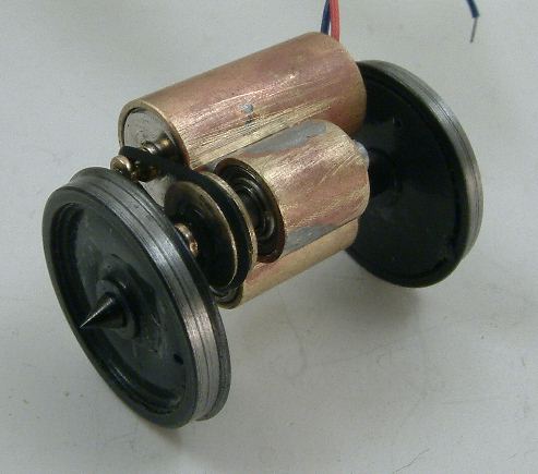
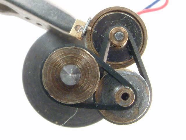
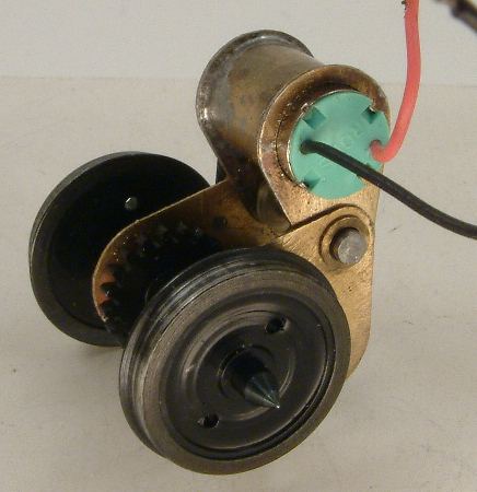
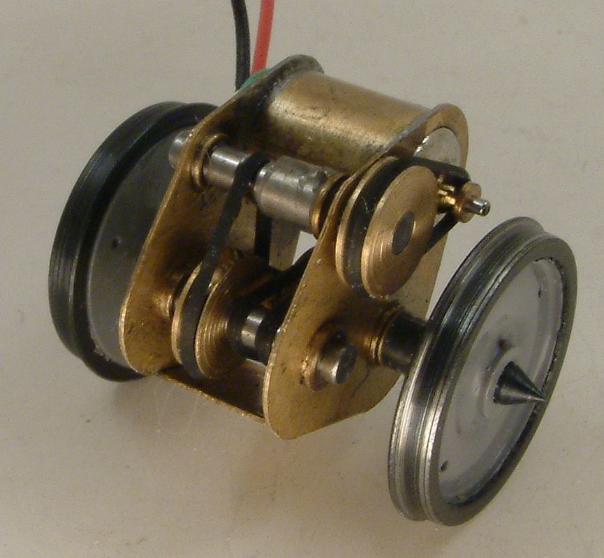
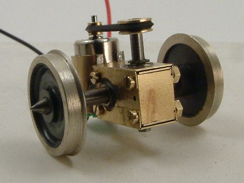
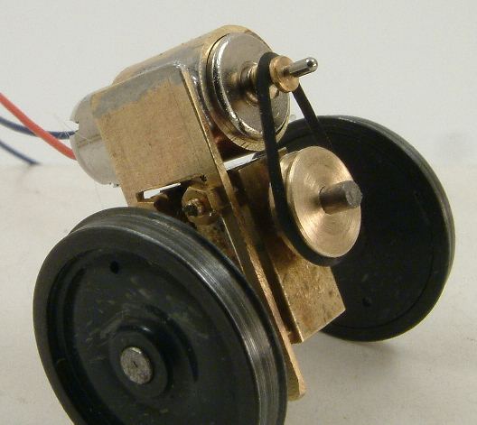
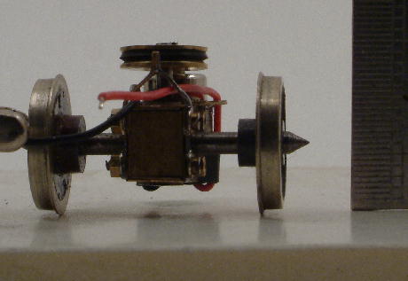
This double-stage unit uses 7mm o.d. tube for carrying the motor, and a 6mm o.d. tube soldered parallel to it to provide the required centre spacing and to carry the 5mm o.d. ball races. A third tube, 7mm o.d. sleeved over a 6mm o.d. tube, provides the spacing and carries the axle, also in 5mm ball races, soldered to the first two in a triangular formation. |
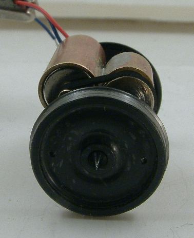
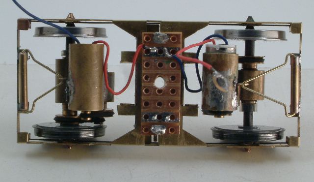
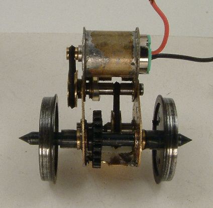
| This end view is taken with the insulated wheel removed, and the crocodile clip is holding the solid steel wheel. |
|
|
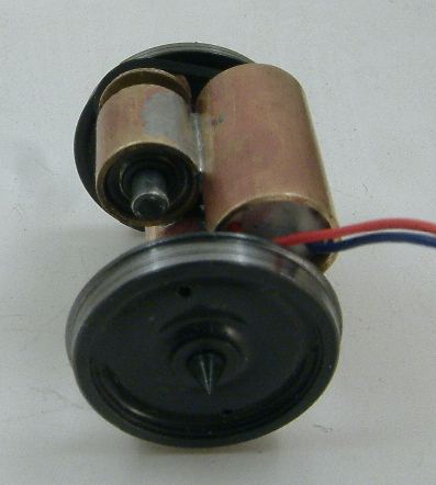
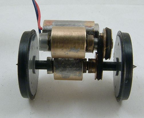
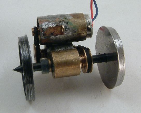
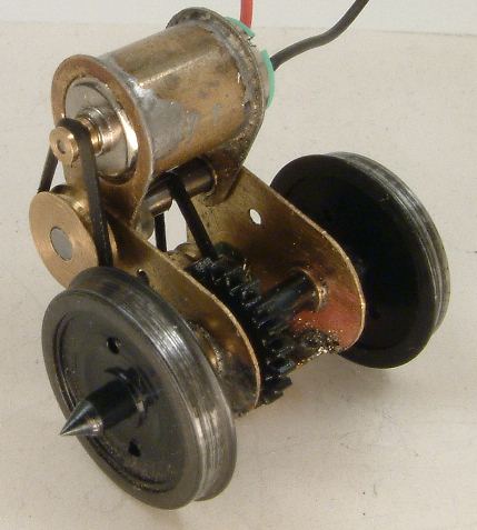
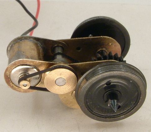
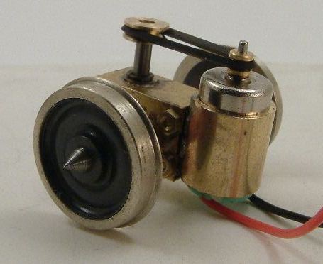
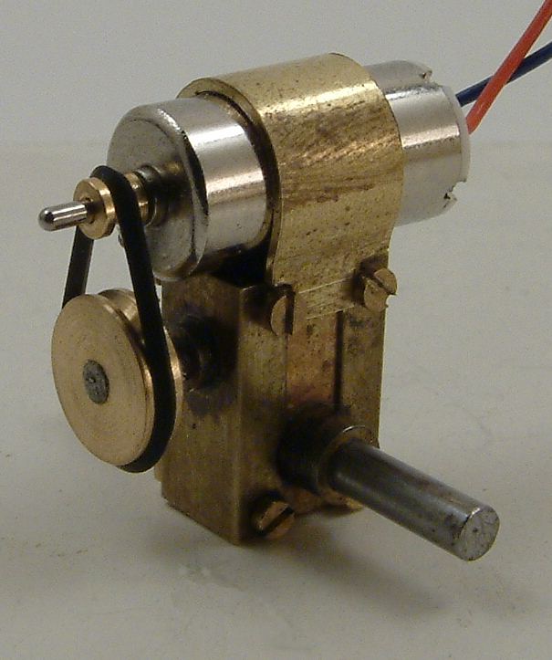
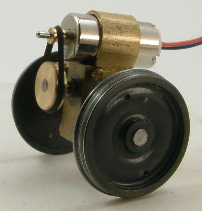
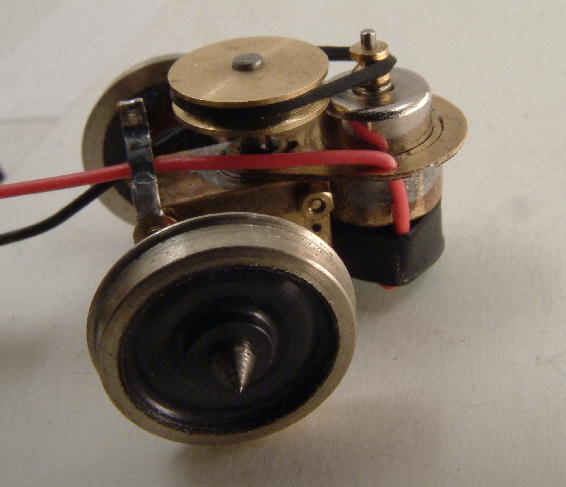
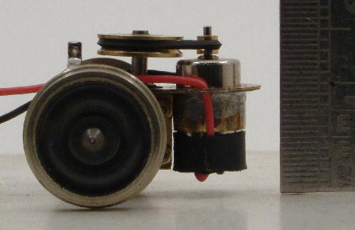
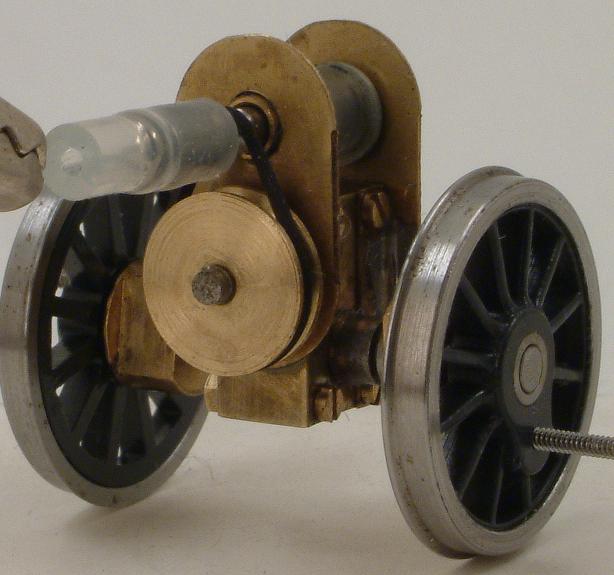
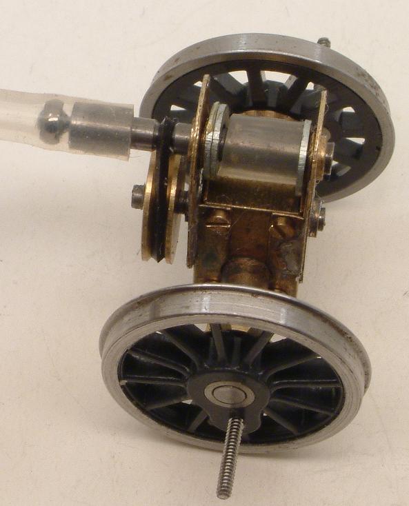
Here are revisions dispensing with the ball races and the sleeved tube on the axle.
Instead, Alan Gibson small frame bushes have been fitted within 1/4" brass rod drilled for the bushes. A flat has been filed on the side of the brass rod mating with the motor tube, to maintain the spacing. In the upper picture, the pulley to the axle is on the inside of the one from the motor. In the lower picture, more space between the wheels has been created by arranging the second stage reduction to the other end of the intermediate shaft. This allows a little more freedom in the positioning of the motor and pulleys, and frees space for the fitting of inside bearings. The formation is now 'L' shaped, rather than triangular, providing more space for a larger final drive pulley. By opening out the 'L' further, space for reducing the back to back to P87 or '00' would be available. The soldering becomes trickier, however. |
|
|
|
|
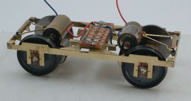
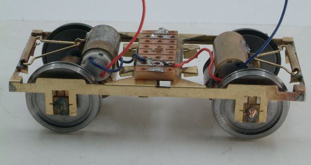
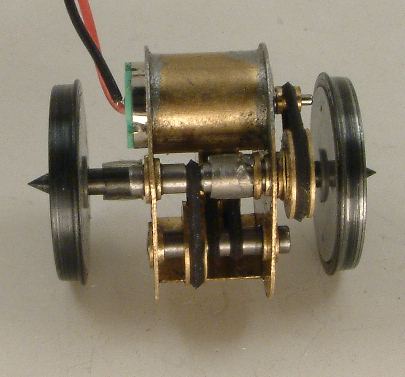
Motors fitted to a Bill Bedford 9' wheelbase sprung bogie frame. The original, more compact triangular formation unit is on the left, the later L-shaped formation on the right. There is ample room for either to fit in an 8'6" wheelbase bogie, and even shorter with a little juggling and some underfloor headroom. The torque reaction link brackets are bent from scrap etch after the holes are drilled, and the tubes soldered to the bogie headstocks before the torque reaction wire links are bent up to fit. The target here is for the pivot hole of the bracket on the motor to rest as near as possible to the vertical centre line of the axle, and as far above it as possible within the structure clearances.
The veroboard is retained by pins soldered through the middle holes of the end pads, and soldered to the bogie. The entire bogie is electrically live to the solid wheel side, and the motors wired together in series, the red wire on the left connected to the blue wire on the right. (The two free wires here were for testing with a bench power supply.) The overall gear reduction from motor to axle is approximately 13:1. |
|
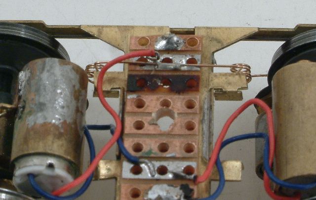
| Completion as a self-propelled bogie. The phosphor-bronze wire soldered to the second vero pad from the top is formed into coils, which reduce the contact pressure of the stylus ends which press onto the tyres. The red wire from the motor on the left is soldered to this same pad, and the blue wire from the other motor is soldered to the pad at the bottom of the picture, the one with the through pin. This completes the circuit from the track. |
|
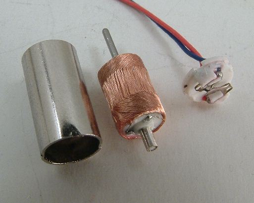
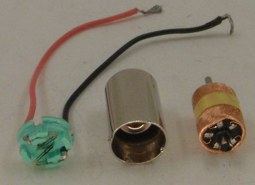
Showing elements characteristic of coreless design, above is a disassembled 12mm long 3-pole micromotor. Below is a disassembled 10mm long motor, which is 5-pole.
|
|
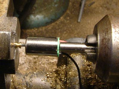
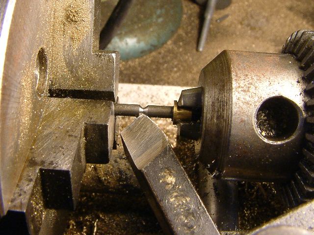
Mounting a pulley on a motor shaft. These motors are delicate. Attempts to push a pulley onto a motor shaft without supporting the back end of the motor results in the end cap departing from the shell. Also, the motor can be damaged if the pulley is pressed onto the shaft without pre-drilling the pulley. The pulleys are therefore drilled with a nominal 0.75mm (30 thou) drill before pressing them onto the shaft. The size of the bore is critical in getting a good fit on the shaft. At this level, the bore size is dependent on the speed of the drill. Turning the chuck by hand, dry, will result in a tighter size of bore compared to running the chuck under power with the same bit, and running the drill with cutting compound will provide a larger bore. These fits will range, respectively, from interference, to close sliding fit, to running fit, so selecting and testing the right drill is very important. Mounting the motor shaft pulley is by pushing a flushfaced blank round (held in the tailchuck) against the end cap on the rear of the motor; the main chuck is opened just enough to allow clearance for the motor shaft, the pulley itself sitting up against the main chuck jaw faces.
|
|
|
|
|
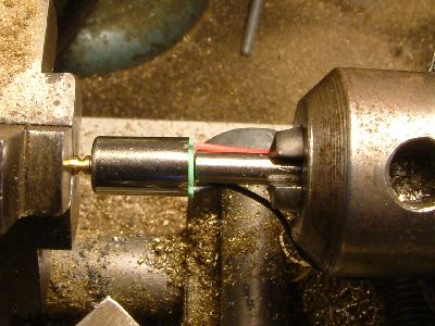
Turning a vee-groove on a 2mm diameter shaft. The shaft is held in the main chuck and is steadied in a tophat bearing held in the tailstock chuck. These turned shafts replicate the function of the very small pulleys and can be used in gearboxes (see diagram below).
|
|
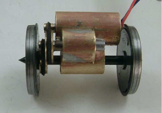
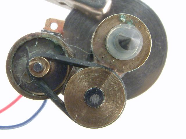
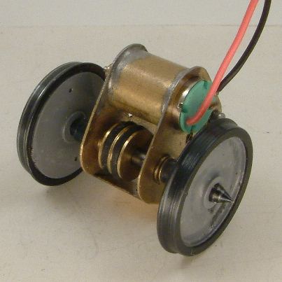
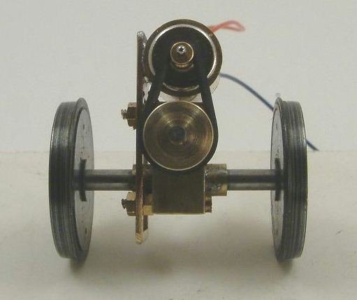
| Four pictures of a triple-stage axle-hung drive with 12:20 Chris Gibbon gears on the final stage. The wheelset is set to 00 back-to-back to illustrate the space available when using the 10mm long motor. The approximate overall reduction is 22:1. (Some pictures of an experimental Class 31 chassis fitted with this configuration of axlehung motor but with 12mm long motors are shown here.) | |
|
|
| These three pictures are of a triple reduction all-belt drive, with double belts on the final stage. The wheelset is set to a 17.8mm back-to-back. 10mm long motor. The approximate overall reduction is 46:1. | |
|
|
|
|
|
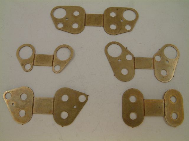
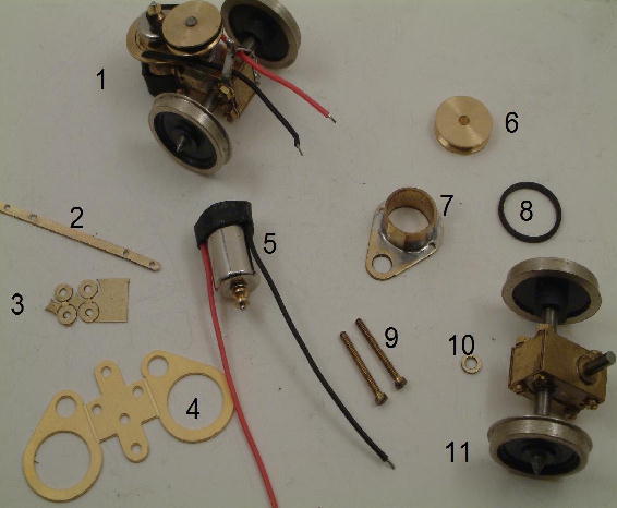
Here are some of the Bill Bedford etches that carry the micromotors.
The shape at the top centre of the image is for a fixed 3-stage unit. The one at the left centre is a single stage with motor, and can be used with the one below it to form a 3-stage unit with the angle of the motor unit adjustable. This can also be used with either one or two (or more) of the bottom right pattern to produce a completely adjustable unit as shown in the drawing above. The right centre pattern is a self-contained 2-stage unit, which can also be used with one of the shape below it to produce a 3-stage drive with the final stage being adjustable for angle. |
|
|
Hybrid belt plus Bill Bedford gearbox drives
Three pictures of a 6mm x 10mm Nigel Lawton motor, with 3mm (nominal) driven pulley and 7.5mm diameter belt, fitted onto the 'bottom' of a standard Bill Bedford 14:1 gearbox. The overall reduction is approx 30:1. The brass motor tube mounted onto the gearbox has been cut through to maintain a good pitch for the above pulley and belt combination. (Use of a 5mm diameter driven pulley results in the 7.5mm diameter belt being too tight, while the 10mm diameter belt is not tight enough. There is possibly room for a tensioner if the 10mm diameter belt is used, subject to it not adding too much extra friction to the system.) 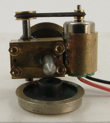
|
|
|
The unit adjacent uses a 6mm x 12mm Nigel Lawton motor mounted on top of a Bill Bedford 14:1 gearbox.
The clamp is made from a piece of 7mm o.d. tube, slit, opened, and crudely shaped to fit. It took the best part of 30 minutes to make. The driven pulley is 5mm diameter nominal. The belt is one of the original 6.5mm diameter. The overall reduction is approx 50:1. |
|
| As an improvement to the clamp above, the adjacent picture shows how a sideplate has been used to set the pitch between the motor shaft and the input axis of the gearbox. The variable pitch enables different combinations of pulley size and belt size to be used, as well as being able to set the degree of belt tension in the chosen combination. The sideplate is attached to the assembled gearbox, the gearbox having been put together with longer 14BA bolts. |
|
|
90:1 (nominal) drive picture key:
|
|
|
|
|
70:1 (nominal) drive This is a gearbox development for a J72 0-6-0 chassis. It uses a normal Bill Bedford 14:1 gearbox, with extra end plates with bearing holes at 6.4mm centres to carry an intermediate shaft. This shaft is from 2mm stock, with a turned groove to locate the Nigel Lawton 7.5mm belt, which drives a 7mm diameter (nominal) pulley. This results in an overall reduction ratio of approximately 70:1. |
|
© Ted Scannell
First issued 11 June 2007
updated 13 June 2007
updated 29 June 2007
updated 9 July 2007
updated 18 September 2007
updated 19 September 2007, belt drive box diagram added
updated 20 October 2007 to add reference to Graham Hickson's page
updated 28 November 2007 to add triple stage belt and belt/gear arrangements
updated 1 December 2007 to add etch descriptions
updated 3 January 2008 to clarify drilling operation for pulleys
updated 18 January 2008 to include hybrid belt plus Bedford box drives
updated 27 January 2008 to include extra hybrid drive pictures
updated 10 August 2008 with details of 90:1 drive
updated 20 October 2008 to show J72 gearbox pictures
| Return to top of page | Safety, privacy and cookies |