.jpg)
Drilling jig for the consistent setting of Scalefour Society conductor rail support components in trackwork
by James Moorhouse
Prototype conductor rails are set at a consistent height and distance from the running rails 1. On our model these consistent settings are also of importance if our track is to resemble the prototype. Additionally, for my needs, there is an even more critical aspect: working pickup shoes will take traction current from the conductor rails. Therefore to maintain contact between the pickup shoes and the conductor rail, consistent gauging is a functional necessity.
The Scalefour Society conductor rail supports 2 maintain the correct height from the sleeper to the top of both the negative and positive rail, but in order to set the gauge a hole needs to be drilled at a determined distance from the rail head in the sleeper, into which the conductor rail support can be inserted which in turn holds the conductor rail at that determined distance from the rail head. In order to achieve consistency in drilling these holes it was necessary to produce a jig.
1 For details, see 3rd and 4th rail dimensions and settings
2 See Conductor Rail Supports component notes.
The following photographs illustrate the jig's construction and use.
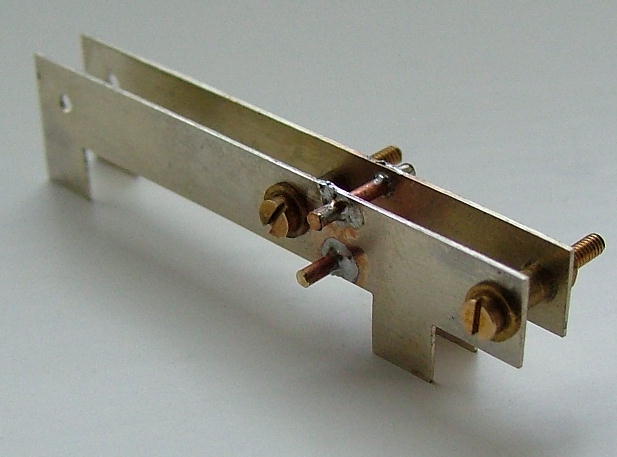
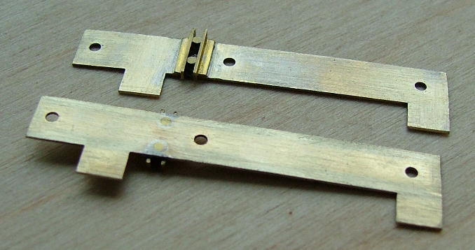
The sides are made from 14thou nickel-silver from some scrap fret. (The drawing below shows the dimensions.) Here two pieces are tack soldered together. Holes have been drilled for 12BA bolts and 1mm brass rod. The holes for the bolts are broached from either side until a bolt can just be pushed through: this maintains the alignment of both sides.
| Two spacers of equal length have been turned from brass tube. The actual length of these spacers is not critical; they go in between the two sides and serve only to keep everything square whilst the two 1mm rods are soldered in place. It is important that the centres of the top and bottom 1mm holes are perpendicular to the top and bottom edges of the sides since the jig will be used either way up.
|
|
|
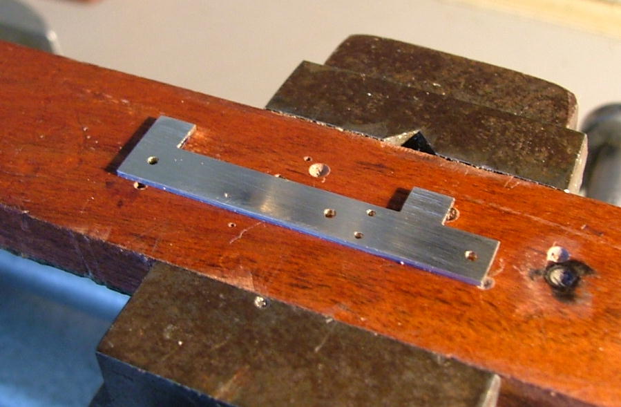
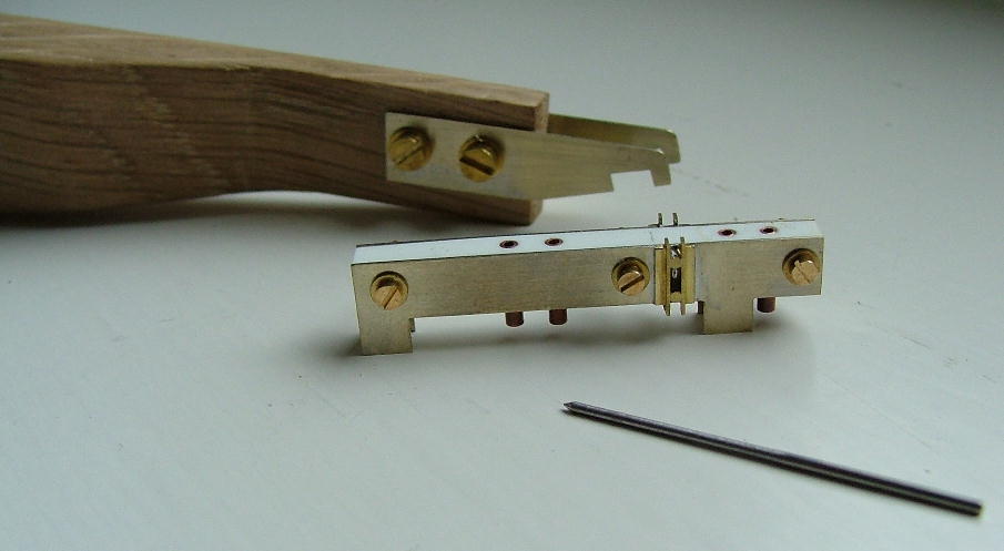
Once the rods have been soldered in place, they are cut between the spacers and trimmed, and any excess solder filed away. The sides of the rods are then gently filed, holding the file square to the long edges of the sides, until the widths of the rods are the same as the width of running rail head. At this stage lengths of brass angle are butted up against the rods and soldered in place. This picture shows the sides once all this had been done. The rod has been cut and filed back and the angle tidied up a little so that only 0.6mm of the angle protrudes above the edges of the sides. This is just enough to get a tight grip on the rail head, but not enough to foul plastic running rail chairs.
The angle pieces protrude above both the top and the bottom edges of the sides. This enables the jig to be used on track or pointwork whose timbers are not perpendicular to the running rails and/or where timbers are 4mm wide. |
|
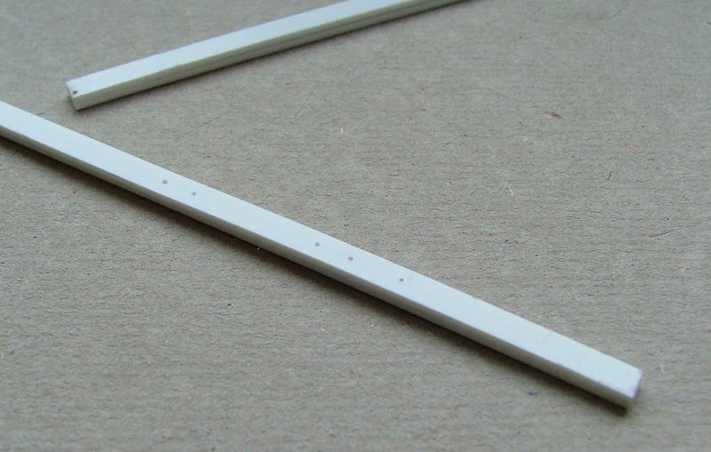
| 40thou plastic strips tack joined at either end with MEK. The strips are nominally 3.3mm wide, i.e. the width of a plain sleeper. It is wise to check the width and consistency of the sleepers you're using first; the sides of the jig need to be quite a snug fit around the sleepers to make sure any hole will be in the middle of the sleeper. The dimples have been marked using a G.W. Models rivet press with a compound slide rest to make sure the centres are set at exactly the right distance apart. Each dimple represents a conductor rail position: as well as third and fourth rail positions, there are out-of-gauge rail positions. |
|
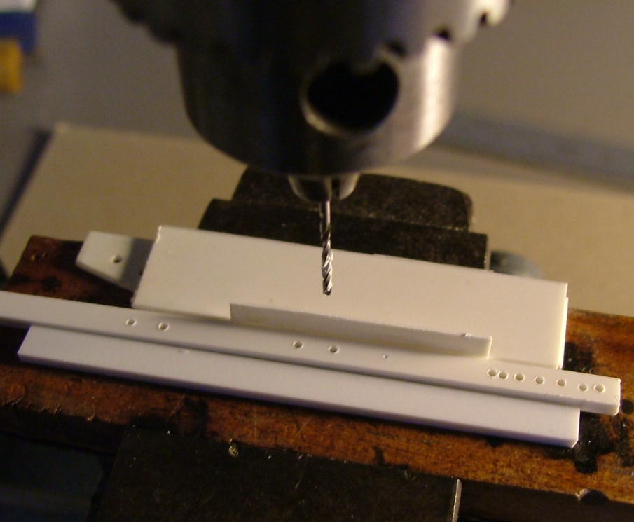
Pilot holes being drilled. I had to practise getting the holes in the middle of the strip as can be seen on the extreme right hand side of the plasticard strip.
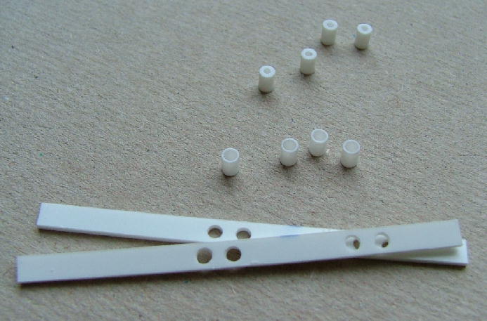
| Strips drilled 1.8mm to accept the bushes. It took me a few goes and strips until I was happy with the positions of the holes in the plastic strips. Also shown on this photograph are some plastic pillars: the front ones have been drilled to accept the bushes; the ones behind will go in between. The pillars have been turned in the lathe to ensure that everything is square when fitted together. |
|
| The bushes were turned from some steel rod with an i.d. of 1.3mm to accept a 1.3mm drill – this is the diameter of the spigot on the bottom of the conductor rail supports. The bushes are a force fit in the pillars. |

|
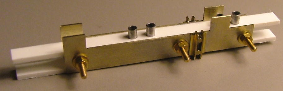
All the components are fitted together and the bolts screwed up tight. I inserted the 1.3mm drill into the bushes to check that they were square to the sides and not leaning over. Once happy a little MEK was brushed around the bushes and left for a few hours.
|
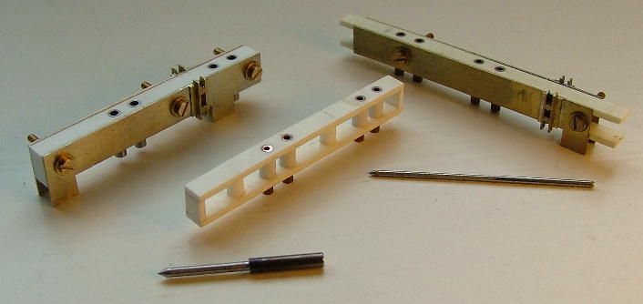
This photograph shows my numerous attempts at getting it right. On the left hand side is the completed jig finished off at the ends with some pieces of plasticard.
At the front is a pin turned to 1.3mm with a point. This is used to calibrate the position of the plastic insert between the sides. The trick is to assemble the jig, place on plain track gauged at 18.83mm, insert the pin in the centre position bush and hit it; then turn the jig around and position on the opposite rail head, insert the pin and hit again. How close the dimples are on the sleeper determines how close the final setting is. Slacken the bolts, adjust the position of the plastic insert and go through the above process again until the dimples are in the same place. The whole process is akin to setting up a mortising gauge to mark the position of a mortise in the middle of a piece of wood. Once satisfied I would use some Loctite 435 to secure everything in place. In the middle of the picture is a plastic insert with 0.9mm i.d. holes. I was using this to drill pilot holes. However, when the pilot hole was being opened out to 1.3mm, unguided, the drill wandered in the thin ply. I was persuaded to go straight in with a 1.3mm drill; this seems fine. On the right hand side of the picture is the mk.1 version – the design differences can be seen. |
|
Here is the mk.2 version fitted with the old plastic insert with 0.9mm i.d. bushes. In the rear is a handle, carved out of a piece of scrap hardwood, used to hold the jig down whilst drilling. It is basically a left-handed copy of a Tamiya scriber handle. I'm not sure how useful the handle will be.
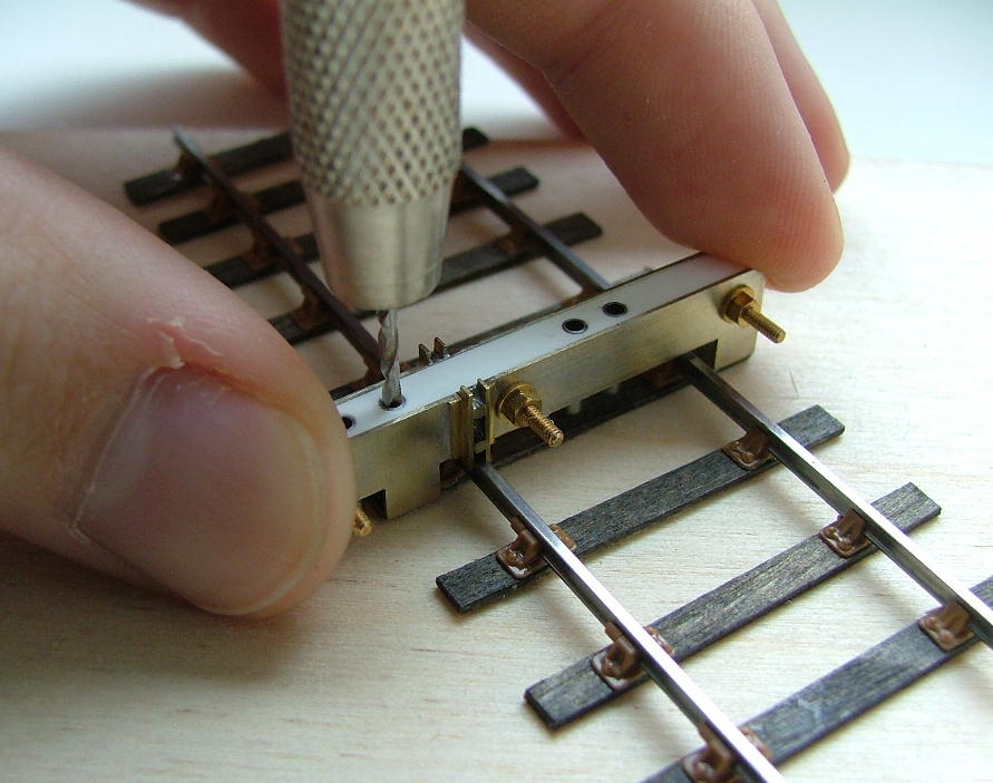
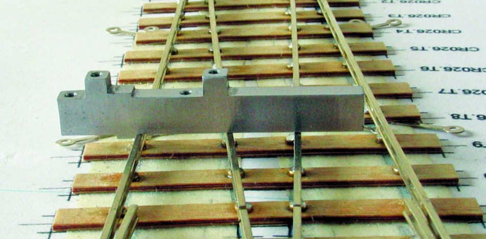
The jig being used to drill a hole for a positive conductor rail support. The sides fit quite snugly around the sleeper thus ensuring that the hole is both in the middle of the sleeper and perpendicular to the running rail.
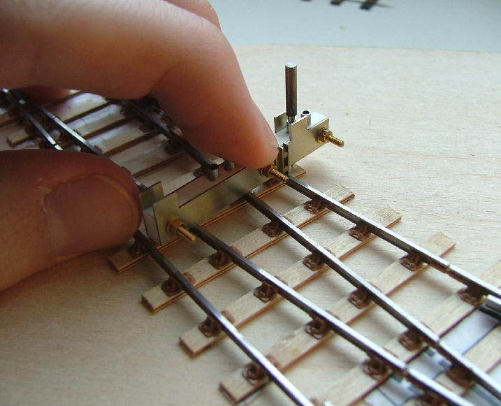
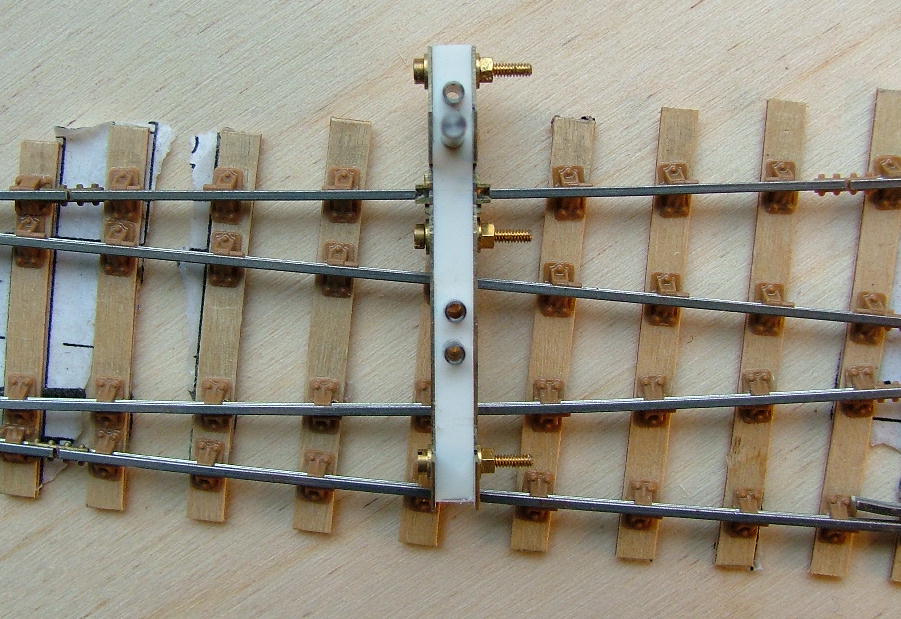
| The jig being used the other way up on pointwork. The jig sits on the tops of the rails and is perpendicular to the rail to which it is fitted even though the timbers underneath are not. To ensure that the hole will be in the middle of the timber I use the pin to check before drilling. |
|
The jig being used on pointwork where the timbers are not necessarily perpendicular to the running rails. Crossing timbers are 4mm wide so the jig could not function the other way up in any case. The use of one jig eliminates any error that comes with using multiple jigs.
|
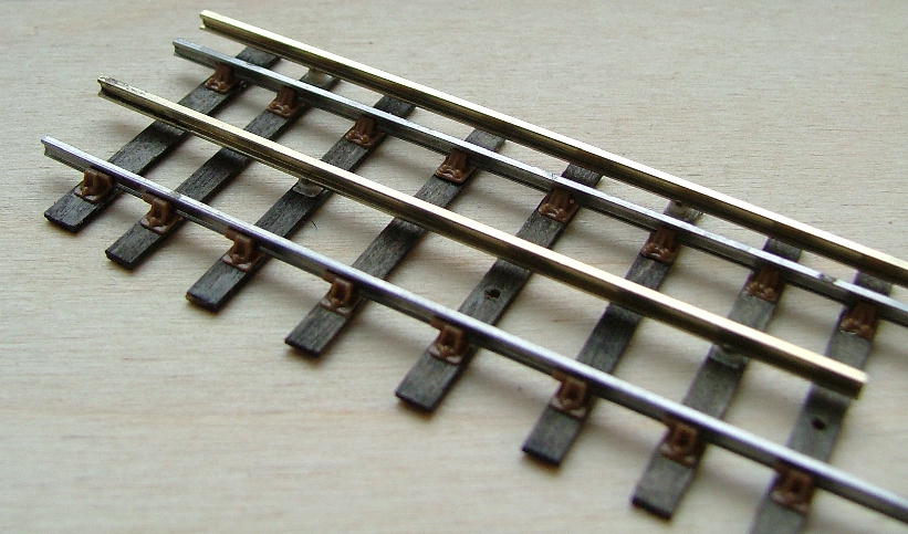
A short length of London Transport plain running line. It is surprising how sturdily the conductor rails are supported. (Holes for out-of-gauge rails can be seen in two of the timbers.) |
|
The evolution of the production version of jig is shown here – 3D printing is great for trying out prototypes, but hopeless for producing actual jigs.
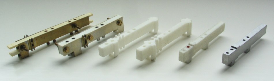
Here is the production version of the drilling jig, now available from Scalefour Stores:
.jpg)
The production version sitting on some track:
© James Moorhouse
21 March 2008
corrected 25 March 2008
production version added 20 June 2014
jig evolution pic added 26 October 2016
| Return to top of page | Safety, privacy and cookies |