|
This page is a draft, and under construction. Comments and contributions are invited.
|
3rd and 4th rail dimensions and settingsby Russ Elliott Acknowledgements: Thanks are extended to Joe Brook Smith, David Smith, Keith Norgrove, Trevor Hurdle, Blair Robinson, Mark Brinton, Mike Peascod, 'Q8', 'Harsig', 'Piccadilly Pilot', Darren Sherwood-Jones and Colin Burnham for providing prototype information for this page, and to David Pirmann, John Turner, Richard Griffin, Clive Feather, Ted Scannell, Len Newman, James Moorhouse, Mike Morant, Geoff Tribe, Pat and David Othen, Martin Hawkes, Dewi Williams, 'District Motorman', Chris Cobley and Trevor Grout for granting permission to reproduce parts of pictures from their collections.
Presentation note: A purpose of this page is to aid 4mm scale modelling, and dimensions on the drawings are given accordingly, except where otherwise specified. Contents Historical overview Standard rail relationships Conductor rail sections Insulator assemblies 'Out of gauge' rails Protection boards Collector shoes Spacing of insulators on plain track Disposition of conductor rails on plain track Conductor rail ramps 3rd rail ramps 3rd-rail side ramps London Transport ramps Safety blocks Conductor rail fishplates and electrical bonding Temperature expansion Conductor rail feeds Termination of conductor rails at point and crossing work |
|
Historical overview The use of conductor rails for railway electric traction supply in the UK dates from c 18901. The City & South London Railway, opened in 1890, used a 500V conductor rail set approximately 12" from one of the running rails and about 1" below them, and required ramps to lift the collector shoes at points and crossings. The Liverpool Overhead Railway was opened on 4 February 1893 and initially had a centrally located conductor rail (energised at 525V), which was relocated to the side in 1905 to enable interworking with the L&Y Railway – the conductor rail was 4" square and set on porcelain insulators above and outside the running rails, with the ends of the conductor rail bent down to form ramps; this latter form can thus be regarded as the precursor of the contemporary standard 3rd rail style. In 1898, the Waterloo & City Railway, operated by and later a subsidiary of the LSWR, had a central power rail (at nominally 520V) level with the running rails. The Central London Railway began working on 30 July 1900 with a central 550V positive rail 1.5" above the running rails. In all these cases, the return electrical path was through the running rails.
Although the Earl's Court experimental system was considered a success, competing technologies again featured in the tenders for the larger electrification project for the Circle line, with the Metropolitan favouring a 3kV 3-phase a.c. system proposed by the Hungarian firm of Ganz & Company. American financial interests were however becoming dominant in the District Railway, and it was effectively taken over during the course of 1901 with the formation of the Metropolitan District Electric Traction Company. A special arbitration tribunal, set up in September 1901 and reporting three months later, recommended the adoption of a d.c. system using 3rd and 4th conductor rails, working at a nominal potential difference of 630V. This system and the settings of the conductor rails became the standard, still used to this day2, and was implemented quickly, with part of the Ealing and South Harrow line opening to the public on 23 June 1903. The last steam-hauled passenger trains on subsurface lines ran in September 1905. The Mersey Railway was the first railway in Britain to convert entirely from steam to electric traction. The NER adopted the outside 3rd rail system in 1904 for its entire coastal suburban network on the north side of the Tyne. The LNWR decided to electrify most of its London suburban system, using 3rd and 4th rails, c 1910. The section between Willesden Junction and Earls Court became operational in May 1914, Broad Street to Richmond in October 1916, and Watford being reached in April 1917. The intimacy of the interests of the LSWR and the District in south-west London led the LSWR to adopt a 600V 3rd rail system c 1913, the first section (Waterloo to Wimbledon, via East Putney) becoming operational in October 1915. The positive conductor rail setting was the same as that adopted for the standard 3rd and 4th rail system, except that the return path was taken through the running rails. Although the LBSCR had adopted a 6700V 25Hz single-phase a.c. overhead system in 1909, and the SECR was planning a 3rd and 4th rail 1500V system, Herbert Walker, the first General Manager of the Southern Railway, made an executive decision to standardise on the LSWR d.c. 3rd rail system, and the Southern Railway grew rapidly to become what is still today the largest urban d.c. electrified railway network in the world. 1 Strictly speaking, honourable mentions should be made of four pioneering narrow-gauge lines:
|
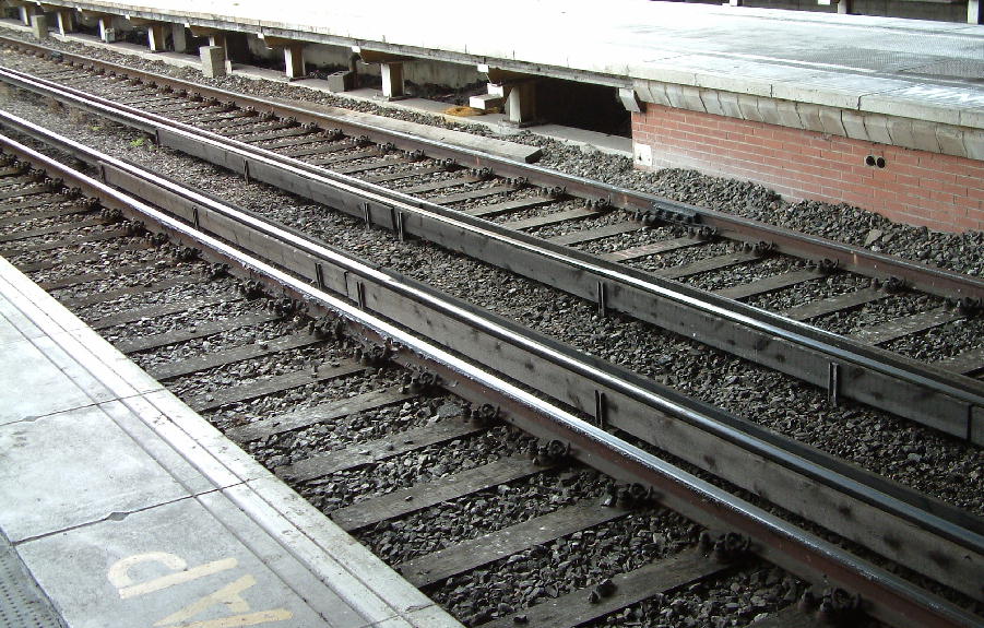
| Standard rail relationships 4mm scale recommended dimensions for the basic interrelationship between prototype-gauged running rails and the 3rd and 4th rails for LT and Southern/SR prototypes are shown in the adjacent drawing. |
Note: The relationships given apply irrespective of the actual rail sections used: the drawing shows the common example of 150lb/yard flatbottom conductor rail with BS95R bullhead section running rail. On the prototype, the distance from the centre of the 3rd rail to the inside face of the adjacent running rail is 1'4" ± 3/8" (405mm ± 10). The top of the outside 3rd rail is 3" + 3/8" - 1/8" (76mm +10, - 3) above the running rails, and the top of the 4th rail is 1.5" (same tolerances assumed) above the running rail height. The negative conductor rail is set equidistant between running rails to a tolerance of ± 3/8" (± 10mm). At one time, LT adopted tighter design tolerances on the height settings, of ± 1/8". Settings for the Liverpool Overhead and Manchester-Bury 4-rail lines differed from the drawing given above, and will be shown in a future annex. The Great Northern & City Railway was opened in 1904 with a power rail outside each running rail, 10" outside and 2" above, supplied at 575V.
|
| Conductor rail sections Four sizes of steel conductor rail section are commonly used: the 150lb/yard section on London Transport surface lines, and also used in some areas of ex-SR third-rail systems; 106lb/yard or 100lb/yard for third-rail systems, e.g. Southern electric; and a rectangular section in tunnels on deep tube lines. | 
|
|
Note: Only those sections commonly used are illustrated. The flatbottom sections all share the same prototype footwidth, at 5.5". Tunnel sections varied: the rectangular one illustrated is 130lb/yard (64kg/m). Smaller rectangular tunnel sections, at 42, 50, 53 and 60kg/m, were also produced, together with an inverted 'U' section used on parts of the Central Line. Upside-down BS95R bullhead can be found in depots and sidings being used as conductor rail. Conductivity, rather than strength or hardness, is intentionally optimised in conductor rail metallurgy; it is softer than running rail, and wears at a greater rate.
On LT, conductor rails are supplied in 60' lengths, but are normally welded together into lengths not exceeding 0.5 mile for straight or gently curved track; this welded length can be shorter on sharper-curved track, but welding is not recommended on curves of less than 15 chains radius. In station environs and accompanying junctionwork, fishplated conductor rails are still predominant. Expansion gaps are incorporated between adjacent lengths of conductor rail. |
|
|
Dissimilar conductor rail sections are welded together in an adhoc manner, as shown here between 150lb/yard flatbottom section and 130lb/yard rectangular tunnel section. White City, 10 August 2003.
Photo reproduced with permission, © 2003 Clive Feather, http://www.davros.org |
|
|
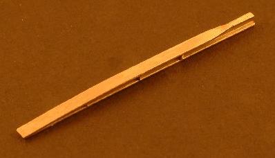
A buttweld of two flatbottom conductor rail sections. The disparity in height between the very worn 100lb/yard and the newer 150lb/yard section is considerable. Caledonian Road & Barnsbury, December 2005. Photo courtesy James Moorhouse.
|
|
|
Modern aluminium-stainless steel composite (ASC) conductor rail (a rolled thin section of stainless steel around the top of an extruded aluminium body), Stratford (Jubilee), 23 June 2000, with a mixture of flatbottom running rail fixings. The composite rail weighs only 16.5kg/m, and its 7mΩ/km conductivity can be twice as good than that of all-steel conductor rail of considerably heavier section. Most concrete sleepers used for 3rd or 4th rail practice have horizontal end and middle lands to keep insulator supports vertical, and are plugged/drilled in their casting stage for insulator fixing holes. Although not visible in this view, conductor support ears fold over and grip the top of the bottom lip of this type of conductor rail; the rail is so light it has to be restrained vertically as well as laterally to avoid displacement. Photo courtesy Ted Scannell.
|
|
|
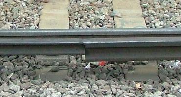
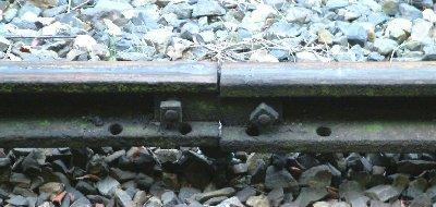
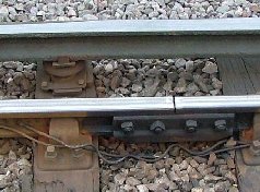
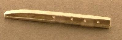
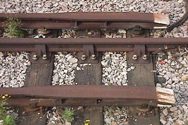
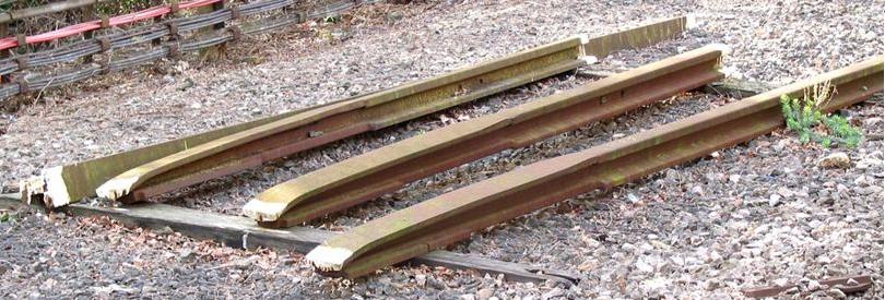
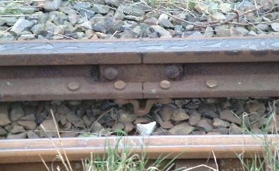
Modern times belie the assumption of the presence of modern equipment. Conductor rails in sidings and terminal tracks are subject to far less wear than heavily-used running lines, so will not be replaced as often, and can be of a considerable ancestry. These two rails, ekeing out their last days at the end of the Bromley North branch on the frugal Southern, appear to be of 106lb/yard or 100lb/yard sections, and evidently came from different original locations, but it is not clear whether they really are of two different sections or if one is merely more worn than the other. Standard Southern 2-bolt fishplate, and both rails have 2 holes in each side of the foot. Bromley North, 16 February 2004. Photo courtesy Ted Scannell.
|
|
|
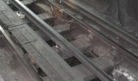
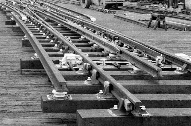
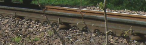
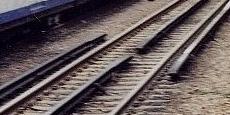
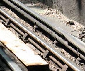
The conductor rail and its adjacent running rail on the Liverpool Overhead Railway, August 1954. The flatbottom running rail (with rail-joints bonded to provide a return path for the traction current) is fixed to longitudinal baulks with screwclamps, the baulks themselves being secured to the rolled steel decking with pieces of angle and wooden wedges. The conductor rail, which appears to be the same section as the running rail, rests in conductor support cradles also fixed to wooden blocks on the steel decking. Owing to a lack of finance to carry out essential repairs to its supporting superstructure, the Liverpool Overhead Railway closed at the end of 1956, and was dismantled between September 1957 and January 1959. Photo courtesy of and © Dewi Williams.
|
|
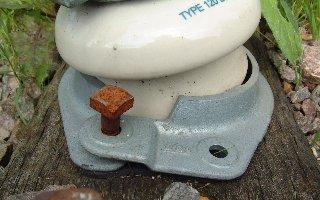
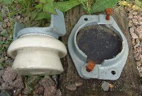
Insulators assemblies (or 'conductor rail supports') Conductor rails are laid on porcelain* insulator assemblies, which have iron cradles on top to locate the conductor rail transversely relative to the running rails without restraining it longitudinally. The insulators are secured to the sleepers by a baseplate clamp, made in two halves, fitting around the base of the insulator.
* On Southern 3rd rail systems, dough-moulded cast resin insulators are now being introduced instead of the more traditional porcelain.
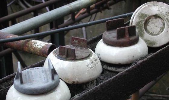
The first illustration shows representative examples of London Transport 3rd and 4th rail conductor supports, with 150lb/yard conductor rail, and '6-bolt' baseclamps. The insulator for the 4th rail is of the same construction as the 3rd rail one, but made to a lower dimension. The 6-bolt baseclamp was superseded by a 4-bolt type, initially of a similar footprint to the 6-bolt type, but later with a rectangular footprint. The last of these appears to have become the standard type of new or replacement fitting c 1946, but many examples of the earlier types can still be seen on the LT system. Special 'double insulators' were specified for supporting the initial part of a negative splay of turnouts, but no photographic evidence exists of these, and standard single insulators are known to be used under negative splays. 
|
|
The illustration on the right shows a Southern standard insulator with 100lb/yard conductor rail.
Packing of insulators appears to be standard, both on London Transport and the Southern, even on new construction. Typical packing thickness on installation is approximately 0.25". As conductor rail wear takes place, the insulators are re-packed underneath, or packing is inserted between the underside of the rail and the cradle of the insulator, to maintain the conductor rail relationship with the running rails. |
|
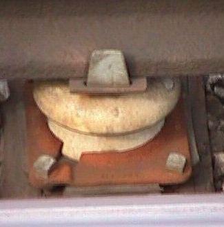
A near overhead view of an LT 6-bolt baseclamp. The baseclamp is packed off the timber, the packing appearing to be such as to clear the two bolts securing the two halves of the clamp together and the 4 coach bolts fixing the support assembly to the timber itself. Leytonstone, 23 June 2000.
|
4-bolt LT baseclamp. Barking, 23 June 2000.
|
|
In both the above pictures, there is a plate fitting over the cradle ears of the insulator, acting as a secured packing piece between the support and the underside of the conductor rail. Pictures courtesy Ted Scannell.
|
|
|
Classical Southern electric porcelain insulators, with different styles of baseclamps. Gravesend, 18 January 2004. Photos courtesy of Len Newman.
|
|
|
Pristine Southern insulators, BR Type 120, showing the way the two halves of the base secure together and hold the porcelain insulator base. Mangapps Railway Museum, 17 September 2005. Photos courtesy Trevor Grout.
|
|
|
|
Insulator sheds and their rail cradles were produced in a bewildering variety. These are special types for rectangular tunnel conductor rail section, photographed on 10 August 2003 at Wood Lane depot. All four of the insulators shown in this picture are different.
Photo reproduced with permission, © 2003 Clive Feather, http://www.davros.org |
|
Dough-moulded resin insulators at Gravesend, 18 January 2004. They have steel ears and baseclamps of a traditional style. The nearside one at the end of a two-bend ramp is of a reduced height. The insulators were probably incorporated as part of a conductor rail renewal program on part of the area, but it is not known why the older porcelain insulators were not reused, since adjacent tracks of the same station have the older type. There is nothing particularly modern about the running rails themselves: standard BS113A flatbottom on timber sleepers. Photo courtesy Len Newman.
|
|
Newer forms of insulator are appearing on 3rd rail systems. The type in the picture appears to have a cast aluminium ear piece, and is now quite common on the North London Line. Caledonian Road & Barnsbury, December 2005. Photo courtesy James Moorhouse.
|
|
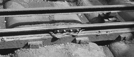
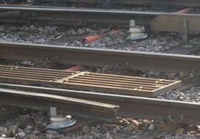
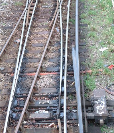
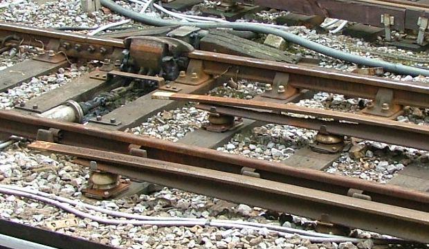
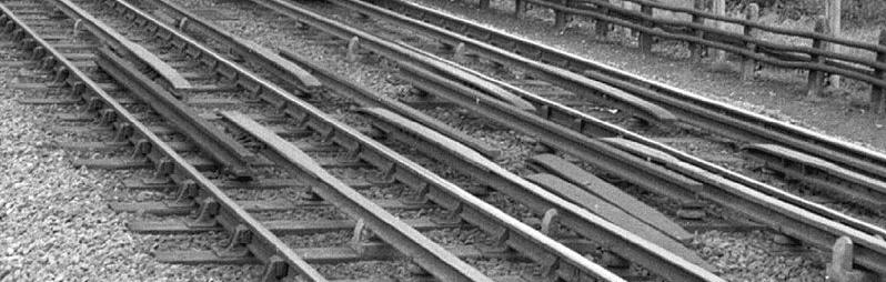
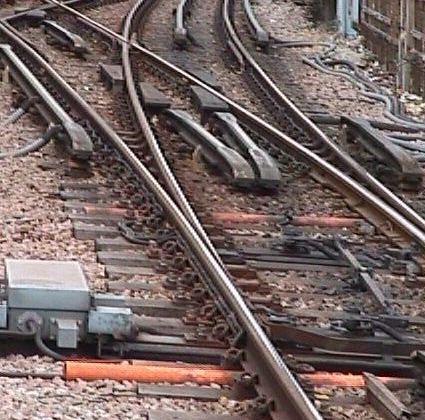
New pointwork under construction at Lillie Bridge yard, August 1959. The turnout, possibly a D12 or D14, has BS95R running rail with 3-bolt running rail chairs and 4-bolt slide chairs. The conductor rail is probably 106lb/yard section: the slight height difference between it and the cast ribbed ramps can be seen, being accommodated by the use of different types of insulator and packing thickness under the conductor rail itself. Note the number of staggered insulators supporting the negative conductor rail splay, the divergent segment of which is machined and bolted (0.75" diameter, at approximately 3'8" centres, in this particular case), together with a wooden wedge in the apex, to the non-divergent segment. (No rule should be inferred from this: negative conductor rails continuous with the diverging path of a turnout are common.) Prominent on the left is an 'out of gauge' rail, mounted on standard insulators, used as an electrical jumper between the breaks in the positive conductor rail. Extended length timbers are used for the five out of gauge rail insulators. The ramp ends have already received their white-paint tips, as have all the running rail chair bolts. The pneumatic switchblade 'chairlock' mechanisms, mounted on the outside of the stockrails, are in white or silver. The actual turnout operating mechanism has not been added yet, and will probably be fitted only at the final 'on site' installation stage. There is no aperture cut into the underside of the negative rail above the toe of the switch; chairlock mechanisms are deemed to have sufficient insulation not to require the aperture. A recommended 75mm minimum clearance applies between a conductor rail and any part of a point operating system, and the use of 106lb/yard conductor rail section provides a little extra clearance to any further connections between the switchblades.
Photo reproduced with permission, © 2003 – 53A Models of Hull Collection |
|
'Out of gauge' rails On London Transport, sections of conductor rail, commonly of life-expired or older section, were used as an electrical 'jumper' between breaks in conductor rails. These are called 'out of gauge' rails. They were commonly employed at pointwork, where they were used as the jumper between breaks in the positive (3rd) rail over the length of the turnout switch, and were in those applications mounted on standard insulators on timbers of greater than standard length. On plain track, conductor rails cannot be given expansion joints, and out of gauge rails are also used as jumpers between these conductor rail breaks. Out of gauge rails were also used as the means via which current was fed from substations to conductor rails. Current London Transport practice prefers cable-bonding to the use of out of gauge rails, although they can still be seen on the system (there has been a programme for their removal during 2003-4). Out of gauge rails are linked to their adjacent conductor rail by wire bonds. The centreline of the out of gauge rail is set nominally 11" from the centreline of the accompanying conductor rail.
The ends of most out of gauge rails are level, but some, probably inherited from District Railway practice, had bent-down ends.
| Protection boards Where fitted, wooden protection boards are spaced apart, symmetrically about the 3rd rail, by nominally 8", and are required not to exceed a certain distance above the running rails, but there may be exceptions to this rule in the vicinity of barrow crossings or level crossings, where extended height boards might be seen.
Depending on the nature of the hazard, protection boards are not always fitted on both sides of the conductor rail, and short single-sided lengths can be found adjacent to turnout operating mechanisms for example. The illustration shows a Southern electric cross-section, with 100lb/yard conductor rail and bullhead running rail. The mild steel support bracket is in this case 2.5" x 0.5" section. The boards have inverted pockets attached to them, and these rest down on the prongs of the bracket. The 45o chamfer on the top of the protection board is on the inside face. Where tripcocks are used, e.g. on London Transport systems, the protection boards are thinner, scaling at approximately 0.35mm thick. |
|
|
Protection board lengths and their support arrangements varied, and depended on site conditions. For normal 10" wide timbers, a protection board support bracket could not be placed on the same timber carrying a support for the conductor rail itself; the disposition of the conductor rail supports took priority, with protection board supports being arranged to suit. For 12" wide timbers, e.g. on pointwork, it is possible for protection board support brackets to be on the same timber as a conductor rail support.
The sketch adjacent should be viewed only as a general guide; the support arrangements for protection boards near complicated junctionwork would dictate some improvisation of the design rules. |
|
|
Canterbury West, looking toward Ashford. The conductor rail protection boards are concentrated in areas where non-permanent way personnel could be expected to work. Two-bend ramps predominate, and there is a side ramp on the turnout on the left. 5 July 2003.
Photo reproduced with permission, © 2003 Richard Griffin, https://www.squarewheels.org.uk/ |
|
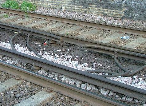
Only the side feed cable seems to be propping up this broken protection board, which is shielding the end of a two-bend ramp. The bending of the ramped section of the conductor rail has been produced by a hydraulic jack. (Prior to this a crowbar would have been used.) The damage to the conductor rail is likely to have been caused by an electrical arc as a result of the failure of a conductor rail support insulator. Worting Junction, 9 September 2003. Photo reproduced with permission, © 2003 Ted Scannell.
|
|
Modern protection boarding at Whitechapel, 12 August 2008. The clips bolted to the board have open tops rather than the previous style of inverted pocket, and the support bracket has a joggle in it on which the clip rests. On modern boarding, the chamfer is over a greater distance, and in this case is, unusually, on the outside face. The board on the right-hand side looks as though it has done previous service adjacent to a ramp. It is possible that this boarding is thinner than the previous norm of 1.5". Both timbers in this picture are 12" wide, and the protection board support on the right is on the same timber as a conductor rail support. Photo © 2008 Ted Scannell.
|
|
Modern Southern protection boarding at Cannon Street, 12 August 2008. The boards are not fitted with clips. The support brackets are cast, possibly in aluminium, with ribs for strength, and the boards are bolted or screwed to them. These boards span 9 timber bays, and are thus in the region of 22.5' long. Photo © 2008 Ted Scannell.
|
Collector shoes Typically, collector shoes are 4" wide.
|
Axlebox-mounted collector shoe assembly on Central Line 1992 stock. Most collector shoes act by gravity, but this type of hangar is non-standard, owing to the need to cater for a non-standard positive conductor rail height on the central section of the Central Line between White City and Liverpool Street*. Modern collector shoes are required to be electrically or pneumatically retractable. Photo taken at Wood Lane depot, 10 August 2003.
Photo reproduced with permission, © 2003 Clive Feather, http://www.davros.org * Because of the way the Central London Railway tunnels were enlarged, they are no longer quite round, and for clearance reasons the outside positive rail is of a special shape and placed 1.5" higher than usual. |
Positioning for 3rd rail collector shoe.
|
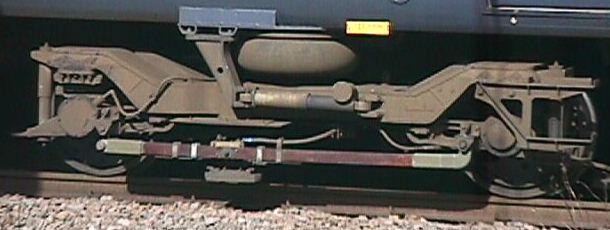
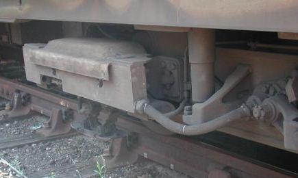
Many collector shoes are spring-mounted from the bogie sideframe rather than being carried by the beam mounted between the bogie axleboxes. On this example of a Thameslink dual-fitted (3rd rail and overhead) Class 319, the shoearm is pivoted off a bracket on the bogie sideframe, and the beam carries the adjuster to set the optimum height of the slipper. Modern shoebeam gear is designed to withstand extremely high peak vertical accelerations, typically in the region of 200 m·s-2. West Hampstead, 28 September 2000, photo courtesy © 2000 Ted Scannell.
|
|
Collector shoebeam and shoe on LT battery loco L20 at Stratford (Central Line), 17 July 2000. The conductor rail at this point is still rectangular tunnel section, and a characteristic tunnel section insulator with 4-bolt clamps (and packing) is shown. Photo courtesy © 2000 Ted Scannell.
|
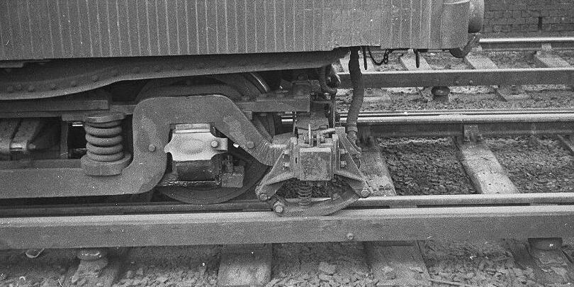
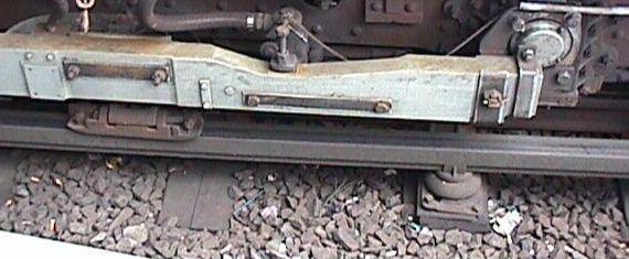
Collector shoe on a 1903-built Mersey Railway driving car, at Rock Ferry, 19 August 1956. By this time the Mersey Railway was 3rd rail only. The shoe assembly is hung off a transverse wooden beam attached to the bogie. The shoe itself is spring-assisted. There is a wooden protection board on one side of the conductor rail. The insulators and their clamps look identical to Southern standard items. Photo courtesy of and © Dewi Williams.
|
LT shoegear - vertical tolerancing The prototype dimensions in the following table are in a context where the tolerance of the conductor rail heights above running rail height is 0.125".
| Swing link type shoes | Rocking link type shoes | |||
| Positive shoe | Negative shoe | Positive shoe | Negative shoe | |
| Free position below conductor rail: | 0.75" | 0.5" | 0.75" | 0.5" |
| Maximum lift above conductor rail: | 2.25" | 1.25" | 1.5" | 1.5" |
| Shoe width: | 4" | 5" | 3" * | 4" |
| * 4" on 1938 tube stock | ||||
Spacing of insulators on plain track There are a number of general rules applying to the placing of insulators on plain track.
Note 2: It would appear that placing 3rd and 4th rail insulators on the same timber was standard for LNWR practice in its London suburban electrification.
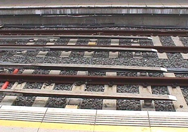
Some modern Southern electric conductor rail supports have cradle ears slightly longer than in previous eras, probably to cope with the effects of conductor rail bounce arising from longer inter-support distances. These supports appear to be spaced every 5 or 6 timber bays. Worting Junction, 9 September 2003. Photo courtesy Ted Scannell.
|
|
There are always exceptions to the rules. Here are positive and negative insulators on timbers adjacent to running rail fishplates at separate locations at Leytonstone, 13 May 2004. Photos courtesy James Moorhouse.
|
|
Disposition of conductor rails on plain track On LT, between stations, the positive conductor rail is normally on the left-hand side of the track in the direction of running. This is however a generalisation, and the hand of the positive rail can be swapped over, typically to even out wear on collector shoes over the longer distances between stations. The swapover is normally associated with an overlap. Swapovers are common in station vicinities to suit pointwork. Reflecting modern health and safety principles, the positive rail is on the side remote from the platform face through stations. In early Metropolitan and District days however, left-hand side positive was the default setting, and was often continued through stations, and thus the positive conductor could be adjacent to the associated platform face. Positive conductor rails adjacent to platform faces could be seen at many Metropolitan and District stations into the early 1930s.
|
|
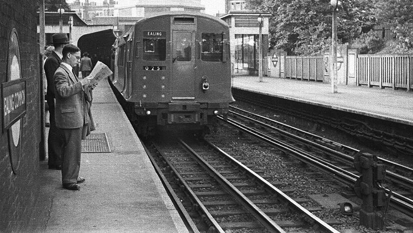
Contrary to the 'rules', District Railway practice still prevails with the positive conductor rail adjacent to one of the platform faces at Ealing Common, although there are crossovers immediately behind the photographer (note the rotating disc shunt signals) giving access to Ealing Common depot that affect the particular disposition of the positive rail at this location. The District Line train is departing to Ealing, and the passengers are waiting for a northbound Piccadilly Line train. 10 June 1950. Despite the separately fused twin electric red rear lamps, the use of oil handlamps on R stock continued until the stock's demise in 1983. Photo courtesy of and © Dewi Williams.
|
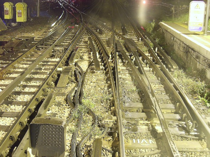
Ealing Common again some 50 or so years later, but this time looking in the opposite direction to the above picture. The extent of the encroachment of the positive rail into the space adjacent to the platform edge is now delimited by modern signs to the passengers. The pointwork is for the northern entry to Ealing Common Depot. Centre-left is a very short positive conductor rail comprising two ramps end to end. It is the last train of the day, returning to depot, on a damp and cool night. 1.50 a.m., 30 September 2005. Photo courtesy of and © 'District Motorman'.
|
| Intentional gaps in conductor rails occur between substation sections, at expansion gaps, substation gaps and section switch gaps. |
|
Where required, a 'dummy' (i.e. unpowered) section of conductor rail, 12' long inclusive of the ramps at both ends, was placed in the normal positive conductor rail position to function as either:
|
|
| On the Southern, the overlap of the 3rd rail is typically 12 timber bays. Apart from keeping its conductor rails away from platform faces, the Southern appeared to have no favoured 'side', even on superelevated track (with perhaps an exception for maximum superelevated lines, where the conductor rail would have been on the inside of a curve), and swapped conductor rail from one side to the other with little hesitation. |
|
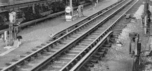
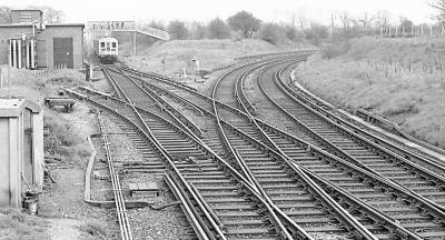
Details of conductor rail practice on bridgework are scarce. This is the bridge at the northern end of Rickmansworth station, pictured in 1958, where a portion of the track on the bridge is ballasted and the other portion plated, with conductor rails precluded from the plated section. Photo Mike Morant.
|
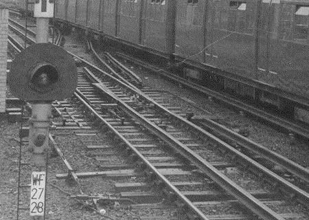
On non-ATP fitted LT lines, every stop signal has a 'trainstop', which is a track-mounted safety device designed to apply the brakes of a train (via a 'trip stop' lever mounted on the train's bogie) inadvertently running through a stop signal. The trainstop is located in advance of its associated stop signal and is mounted on the right-hand side of the track relative to the direction of running. The position of the trainstop mechanism precludes the presence of the positive conductor rail, which is terminated in the normal way by a ramp either side of the trainstop mechanism. Trainstops are provided with wooden ramps to protect them from damage by loose collector shoes. The picture shows trainstops provided for both directions of running in one of the terminal tracks at Hammersmith (Metropolitan); the incoming trainstop is lowered only when the speed of an incoming train is confirmed to be less than approximately 10mph. 8 March 2004. Photo courtesy James Moorhouse.
|
|
| Conductor rail ramps Ramps differ in style. For 3rd-rail systems, the conductor rail is bent down below its normal datum height, whereas London Transport uses horizontal-base cast or prefabricated ramps. This is a generalised picture; the Southern is known to have some horizontal-base ramps in locations subject to regular flooding. It is also a generalised picture in respect of London Transport, which has ramps formed from plain rail.
3rd-rail ramps Early ramps were bent in two places, but are being superseded, as train speeds increase, by the newer practice of a single-bend ramp. The end of the ramp is normally supported on a shallow insulator. Depots and the low speed tracks of crossover roads can have ramps of a gradient steeper than shown here. The extent of the deployment of single-bend ramps is not known, and two-bend ramps still appear to be the norm, at least in most urban areas, where speeds are generally low. |
|
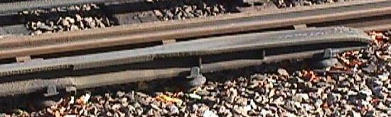
One of the very shallow types of support under the end of a two-bend conductor rail ramp. The diameter of this 'Type D' insulator, at approximately 225mm, is greater than that of the shed of a normal height insulator. The black deposits on the ramp are probably leaf mould, well baked on with regular doses of a few hundred amps. Note the 2-bolt conductor rail cable feed, on the other side of the ramp. Blackheath, 25 January 2004. Photo courtesy Ted Scannell.
|
The type of insulator chosen to support the end of a ramp will vary according to the running and conductor rail sections used, and the nature of the bends achieved in the actual ramp. The height of this insulator is between that of the very shallow ramp type and a normal conductor rail insulator. Lewisham, 16 February 2004. Photo courtesy Ted Scannell.
|
|
3rd-rail horizontal-base flood ramps. In 2004, the New River burst its old cast-iron water main in Wallace Road, Canonbury, causing severe flooding to Canonbury station. The main was subsequently repaired, but the existing expansion gap in the westbound platform was renewed in a precautionary measure with horizontal-base 'flood' ramps, which are formed of normal conductor rail whose web has been flame-cut out and the top bent over to a gentle curve. Note the double cable bonding, with cable spade terminals bolted to angle brackets fixed to the rail. Canonbury, 2 August 2005. Photo © Russ Elliott.
|
|
|
Horizontal base fabricated ramps with unsupported ends, Caledonian Road & Barnsbury December 2005. Photo courtesy James Moorhouse.
|
| 3rd-rail side ramps To avoid gaps in the conductor rail for a whole train, conductor rails may need to be made continuous over the higher speed track of a turnout, and collector shoes of trains on the low speed track are raised onto the surface of the conductor rail by the use of a 'side-entry ramp' bolted to the inside of the conductor rail. Side-entry ramps are avoided if possible, as the impact between the ramp and the collector shoe can cause heavy wear on both the ramp and the collector shoe, and a low speed (typically 20mph) restriction applies for trains approaching the ramp from the side. They are usually seen only in areas of concentrated pointwork.
More commonly, side ramps are also provided to act in a trailing mode at many turnouts, to maintain collector shoe contact for as far as possible, and are intended to be traversed only in the trailing ('off') direction. A typical side ramp is illustrated. |
|
Note: Although largely confined to 3rd-rail systems, London Transport is known to have some side ramps, although their use is now deprecated. Modellers should be aware that current practice is not necessarily a good indication of previous LT eras.
|
|
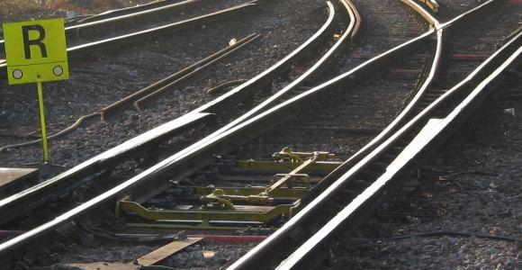
Side-exit ramps, in this example generously on both sides of a facing (junction) turnout. This turnout is not used in the trailing direction. Ascot down main, looking west, 18 March 2003.
Photo reproduced with permission, © 2003 Richard Griffin, https://www.squarewheels.org.uk/ |
|
Top view of a side ramp on a 1:8 bullhead single slip at Bromley North, 16 February 2004. This ramp is used only in the trailing direction. Note the protection board between the conductor rail and the electric point motor mechanism. Photo courtesy Ted Scannell.
|
|
Side exit ramp, bolted to what seems to be 150lb/yard conductor rail section, for a facing junction point. In the top left there is an end of a two-bend ramp on a shallow insulator. Lewisham, 16 February 2004. Photo courtesy Ted Scannell.
|
|
Side ramp alongside a D-switch bullhead turnout. Bromley North, 18 February 2004. Photo courtesy Ted Scannell.
|
|
|
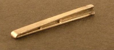
London Transport horizontal base ramps Prototype ramps are usually butt-welded to the conductor rail. The model pictures show nickel-silver lost-wax 4mm scale ramps available from the Scalefour Society.
|
|
Cast type (with ribs): 4'6" (18mm) long, for speeds up to 60km/h - up to 1958. The slope of this ramp is 1:30.
|
|
Low speed fabricated type: 5'0" (20mm) long, for speeds up to 60km/h - for new works after 1958
|
|
High speed fabricated ramp: 10'0" (40mm) long, for speeds up to 100km/h - post 1958 installation
|
Ramp pictures by Ted Scannell
|
|
An LT conductor rail to ramp weld, White City, 10 August 2003. The insulators have 4-bolt clamps.
Photo reproduced with permission, © 2003 Clive Feather, http://www.davros.org |
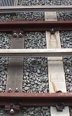
Cast ribbed ramps at Barking, 23 June 2000. Negative and positive ramps are normally terminated simultaneously, as typified here, so negative and positive insulators have to be placed on the same timbers. Photo courtesy Ted Scannell.
|
Cast ribbed ramp at Snaresbrook, 17 October 1999. Photo courtesy Ted Scannell.
|
LT is meticulous at providing ramps in any terminal tracks, even where no trains will ever run, but the reasoning for the extravagance of these long (approximately 3.6m) high-speed types at the concourse end of Stratford (Jubilee) is not clear. They are attached to the composite conductor rail with 4-bolt fishplates. 23 June 2000. Photo courtesy Ted Scannell.
|
Modern fabricated LT ramps awaiting installation, at Amersham, 10 February 2004. These are made from 74.4kg/m flatbottom conductor rail section with a steel plate welded to a ground-off head section. A recess in the foot has also been ground off.
Photo reproduced with permission, © 2004 Richard Griffin, https://www.squarewheels.org.uk/ |
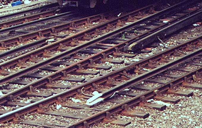 Ancient lore in the heartland of the North Western. This is the southern end of Willesden Junction, on the Bakerloo line, the two prominent tracks converging to the left of the picture to form the station bay. None of the ramps here are of the conventional cast or prefabricated LT style with their characteristic widened 'nose'. The positive 'on' ramp in the top right (shielded by protection boards) and the negative 'off' ramp in the bottom centre (unusually, bonded to the running rail) have been formed by cutting out the web of conductor rail (100lb/yard or 106lb/yard section throughout this location) over a distance of approximately 2', bending the top face down, and rewelding the join. The positive 'off' ramp in the top left of the picture is plain conductor rail bent down; its base is not horizontal, although the degree of bending is not as marked as that of the style of the Southern. The turnout (not visible in this picture) joining the left-hand track has one arm of its negative splay truncated. London Underground trains are not permitted to use the bay at Willesden Junction, and every characteristic here remains substantially as it was built 80 years previously by the LNWR. 28 May 1996.
Photo courtesy of and © Pat & David Othen. |
|
LT ramps in sidings are often made by flame-cutting out the web of light-section conductor rail and bending the top down. The ends of the ramps are therefore not flared in width as per the normal LT ramp style. Note the pneumatically-controlled 'derailer', which substitutes for a trap switch at this space-starved location. Edgware Road, 23 October 2005. Photo courtesy James Moorhouse.
|
|
|
The extremely restricted space in Edgware Road sidings dictates improvisation, and here is a very short snub ramp attached to the conductor rail with 2-bolt fishplates. You can see exactly where the negative shoes clout it. Edgware Road, 23 October 2005. Photo courtesy James Moorhouse.
|
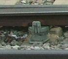
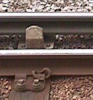
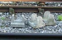
Safety blocks Cast concrete safety blocks are commonly used towards the ends of LT conductor rails, before the welds to the ramps themselves, to act as a lateral safety measure if conductor rails are dislodged from their supports. They do not provide any vertical support to the conductor rail. They are bolted to the timber, and existed in two heights, to cater for positive and negative conductor rails. It is thought that safety blocks were used from c 1930 onwards.
|
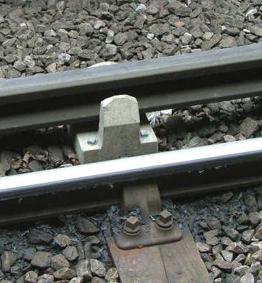
Safety block at Acton Town, 7 March 2004, with bullhead running rail. Picture courtesy of James Moorhouse.
|
|
| Conductor rail fishplates and electrical bonding On LT, fishplates for 150lb/yard conductor rail section were of 2-bolt design, 8" long, with 4" fixing centres, and for 130lb/yard tunnel conductor rail section were of a 4-bolt design, 12" long, with 3" fixing centres. Multistrand crimped copper wire bonding across the joint optimises electrical continuity.
Current Southern electric practice favours continuous welding of conductor rail, up to a maximum length of approximately 550m, rather than the previous practice of using 2-bolt fishplates. |
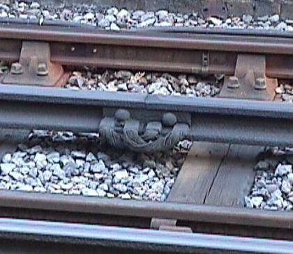
150lb/yard conductor rail 2-bolt fishplate joint and bonding, Snaresbrook, 17 October 1999. Photograph courtesy Ted Scannell.
|
|
2-bolt conductor rail fishplate, with a 4-bolt (or maybe 8-bolt?) electrical continuity sprung fishplate on its underside. There is no visible sign of the conductor rail joint on the greasy top surface. The conductor rail appears to be 150lb/yard section. Bromley North, just after a rain shower, 16 February 2004. Photo courtesy Ted Scannell.
|
|
Temperature expansion Temperature expansion gaps cannot be provided in long lengths of conductor rail. On the Southern system, electrical continuity is ensured by joining lengths of conductor rail with cable bonding or by swapping the hand of the 3rd rail, with an overlap between the two sides if necessary to prevent 'gapping'. On LT, expansion gaps are linked with cable bonding or by the use of out of gauge rails as electrical jumpers between the parallel gaps in the conductor rails.
|
|
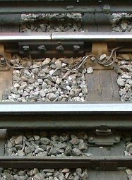
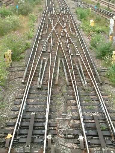
Standard LT expansion gap. These parallel gaps are joined electrically by 'out of gauge' rail jumpers linking their respective conductor rails, the wire bonding being attached to the web of the ramp. Each jumper is supported by three insulator assemblies, spread over seven timber bays. The positive out of gauge rail insulators are carried on normal length timbers slewed tranversely to accommodate the placing of the out of gauge rail. Officially, such out of gauge timbers were specified as 9'6" long, i.e. 1' longer than a standard timber. The positive out of gauge rails are carried on standard positive rail height insulators, and the negative 'between gauge' jumpers are carried on standard lower negative rail height insulators. Concrete safety blocks are present for all the ramps, and each long ramp is supported by two insulators. Most of the conductor rail in this view seems to be 106lb/yard section, but the positive and possibly the negative rail on the near right-hand side of the picture looks to be in the heavier 150lb/yard section, as is each of the four jumpers. The ramps are all long fabricated types except for the facing ones on the up line on the right, which are a shorter cast type of ramp. The Metropolitan appeared to favour a mixture of left-hand and right-hand positive rail orientation between stations, probably to even out wear on collector shoes. North Harrow, July 1957.
Photo reproduced with permission, © 2003 – 53A Models of Hull Collection |
Expansion gaps, Southern style, with simple cable bonds, one being held with sections of cast trunking. Ewell East, 28 March 2004. Photo courtesy James Moorhouse.
|
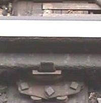
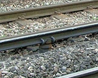
To allow temperature expansion, but to prevent longitudinal creep, the conductor rail is secured. On LT, an 'anchor insulator assembly', or groups of them, is used for this purpose. These are placed usually at the midpoint of the conductor rail, and the number of assemblies required depends on the length of conductor rail to be anchored. On the Southern, a 'fair' clip was used either side of an insulator to grip the conductor rail.
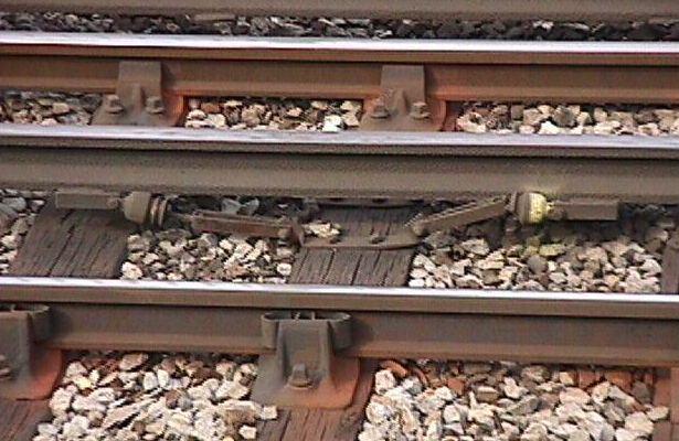
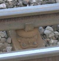
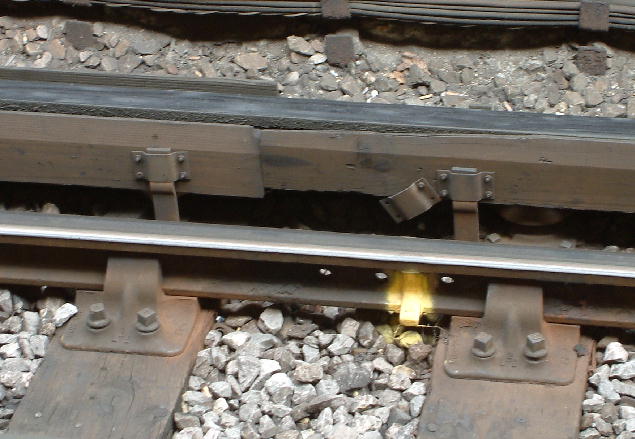
A conductor rail anchor assembly on a negative rail. There are two straps bolted to the timber, one either side of the conductor rail. Note the small insulators between the pieces welded under the rail and the rest of the assembly. Barking, 23 June 2000. Photo courtesy © 2000 Ted Scannell.
|
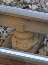
A 'fair' clip, either side an insulator. It is common for pairs of fair clips to be deployed in duplicate on adjacent conductor supports. Ewell East, 28 March 2004. Photo courtesy James Moorhouse.
|
Conductor rail feeds Conductor rails are fed via substantial armoured cables. The electrical arrangements and systems for feeding and linking conductor rails can, of necessity, be complex, and are therefore somewhat outside the scope of this article.
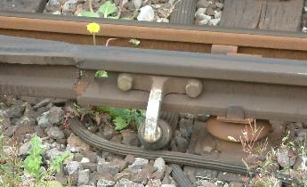
On 3rd rail systems, the favoured location for a conductor rail feed in modern times appears to be half-way along the first bend of a two-bend ramp. Photographic evidence of earlier eras indicates that the favoured location was probably different, and commonly a short distance before the beginning of the ramp.
Generally, sections are usually fed by substations from both ends ('double end feed'), whilst terminus road, sidings and depot roads are fed from one end only ('single end feed').
|
An excellent video, 'London Underground - Traction Current: Alive or Dead?', produced in 1989 by Spa Films Ltd for London Underground Limited, and giving much detail about conductor rail feeding arrangements, rail gap indicators, section switch cabinets, and working procedures for the disconnection and reconnection of the traction supply.
For information on the Youtube cookies you might receive if playing this video, please read the privacy policy and cookies page before you play it. |
|
Detailed view of hook switch in the closed position, which connects the conductor rail with the cable.
|
|
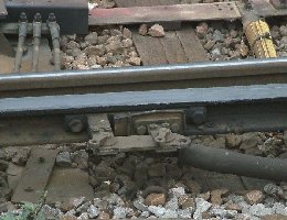
This conductor rail has a normal permanent connection to the middle of the first bend of its ramp. On the right-hand side is a 'hook switch', with its copper bar swung into the open position. Hook switches are operated manually to connect or disconnect feeds from the local substation, or to link sections of conductor rails to feeds from adjacent substations when a local one, or one of its circuits, is undergoing repair or maintenance. Both pictures taken at Lewisham, 16 February 2004, courtesy Ted Scannell.
|
|
|
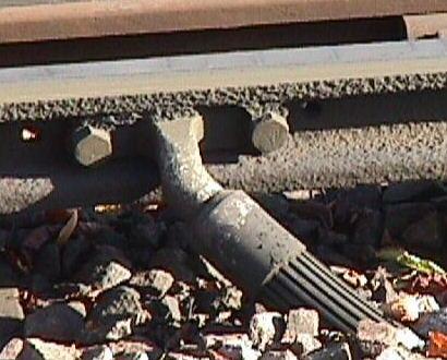
Conductor rail cable feed, Snaresbrook, 17 October 1999. The cast copper terminal lug is 9.375" long, with the fixing centres at 7.5" for the phosphor-bronze bolts and nuts. Terminal lugs like this existed in right-hand and left-hand versions. The outside diameter of the cable is approximately 3". The conductor rail is very worn. Photo courtesy Ted Scannell.
|
|
A 'right-angle' style of conductor rail cable feed, with dimensional details identical to the Snaresbrook example above. This style derives from the original District Railway style. Upminster, 21 July 2005. Photo courtesy Ted Scannell.
|
|
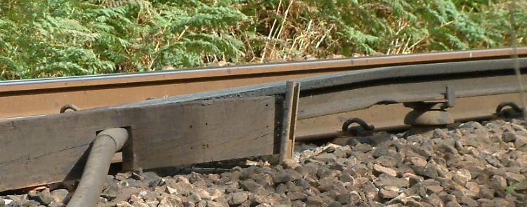
An example of a substation feeding arrangement, which provides sectional insulation either side of the substation. Here, separate sections of out of gauge conductor rail are joined mechanically with each other (for stability purposes) but electrically insulated from each other, by wooden (typically teak) fishplates. The disposition of the connections between the cables and the out of gauge rails will depend on which side of the running line the positive conductor rail is located. Different lengths of ramp from those shown here can be fitted to these substation gaps, as per the standard expansion gap.
The equivalent arrangement for tube tunnels is different, using a single out of gauge rail for the negative conductor rail feed, as per the drawing, but with separate and segregated copper busbar sections feeding the positive conductor rail sections. |
|
|
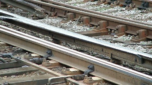
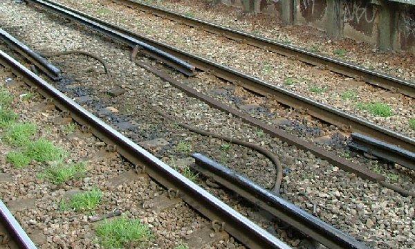
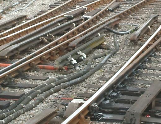
The cable feeding arrangements in areas of more complex trackwork sometimes lead to adhocery and improvisation. Here, a short (approximately 12') length of out of gauge rail, mounted on extended turnout timbers at its usual 11" centre spacing from the positive conductor rail, is being used as a method of joining positive feeds, as well as its more usual function of connecting to its adjacent conductor rail by wire bonds. The extended length timbers in this bullhead area possibly date from a time when out of gauge rail linking was the norm. Upminster, 21 July 2005. Picture courtesy of Ted Scannell.
|
|
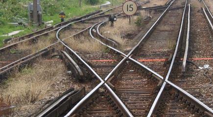
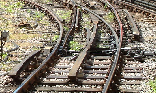
| Termination of conductor rails at point and crossing work In setting out conductor rails at point and crossing work, the prime consideration is the avoidance of 'gapping', a situation where none or few of the collector shoes are in contact with conductor rail. Locomotives and many stock sets have only 4 collector shoes, and in station areas and sidings, speeds are often low, and locos and stock will be able to coast without power only over short distances. In complex pointwork areas, or in situations where traction power and acceleration is necessary throughout a set, side exit ramps are commonly used to minimise gapping. Side entry ramps are used only where absolutely necessary.
Short lengths of conductor rail are avoided if possible, since they are difficult to restrain, but are in many cases necessary for crossovers, where side-entry ramps for the normal direction of running would be inadmissable. |
|
Guidelines for some general setting out rules and clearances for 3rd-rail systems are illustrated.
A worked example of part of Wye. Here, the main crossover is equipped for use by electric stock, but the loop is not. The side exit/entry ramp and the two short conductor rails prevent gapping of stock traversing the crossover. The two short conductor rails are kept clear of the path of collector shoes of through trains, and one of them concedes priority to the conductor rail on the down through route. For down trains, there is an unavoidable absence in the conductor rail over part of the slip, but there are no other discontinuities that would subject a train to gapping. The up conductor rail encroaches into the platform length, but swaps over as soon as it can after a suitable overlap.
|
Conductor rail and ramp termination for LT turnouts are given in the following table. The dimensions in the table apply only to turnouts with continuous non-segregated negative splices.

|
Switch type |
Crossing angle |
Dimension to tip of ramp |
Out of gauge rail length |
|||
| x1 | x2 | x3 | x4 | |||
| A | 5.0 5.5 6.0 6.5 7.0 7.5 8.0 |
62.3 62.3 62.3 62.3 62.3 62.3 62.3 |
108.5 108.8 110.5 111.3 111.8 111.9 111.9 |
69.7 76.1 81.4 86.3 91.8 91.8 92.7 |
10.4 11.6 12.1 13.6 14.2 14.9 15.9 |
117.7 117.7 117.7 117.7 117.7 117.7 117.7 |
| B | 6.0 6.5 7.0 7.5 8.0 9.0 10.0 11.0 |
80.3 80.3 80.3 80.3 80.3 80.3 80.3 80.3 |
133.3 134.6 136.2 137.2 138.3 138.3 138.3 138.3 |
82.8 89.1 94.3 100.4 105.9 106.4 110.3 116.4 |
12.3 13.2 14.5 15.3 16.3 18.0 20.0 22.0 |
135.7 135.7 135.7 135.7 135.7 135.7 135.7 135.7 |
| C | 7.0 7.5 8.0 9.0 10.0 11.0 12.0 14.0 |
96.3 96.3 96.3 96.3 96.3 96.3 96.3 96.3 |
165.7 167.9 169.1 171.0 173.0 173.0 173.0 173.0 |
97.7 103.3 105.8 121.4 132.3 132.8 135.8 147.6 |
14.5 15.3 16.3 18.3 20.3 22.0 24.0 28.0 |
151.7 151.7 151.7 151.7 151.7 151.7 151.7 151.7 |
| D | 8.0 9.0 10.0 11.0 12.0 14.0 16.0 |
114.3 114.3 114.3 114.3 114.3 114.3 114.3 |
194.4 198.8 202.8 204.9 207.5 207.5 207.5 |
111.4 123.0 135.9 147.6 158.8 161.4 171.6 |
16.3 18.9 19.6 22.5 24.5 28.0 32.0 |
169.7 169.7 169.7 169.7 169.7 169.7 169.7 |
| E | 14.0 16.0 |
144.7 144.7 |
271.8 276.3 |
189.5 212.1 |
28.6 32.8 |
200.0 200.0 |
| F | 16.0 20.0 |
184.3 184.3 |
334.9 346.0 |
219.4 240.7 |
32.8 39.2 |
239.7 239.7 |
Dimensions in millimetres, for 4mm scale, and apply to non-curved switches.
See also details of turnout lead lengths. |
||||||
For long diamonds on the Metropolitan lines, positive rails were provided within the diamond area itself, and took the plan shape of an elongated X.
|
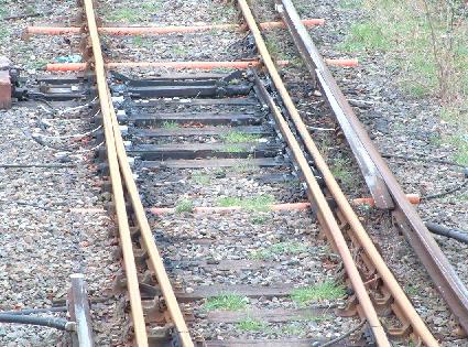
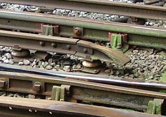
LNWR practice at turnouts differed from LT in that only one leg of the negative splice was extended, for the diverging route in this particular case. It is possible that the truncated arm was not made of rail, but a prefabricated ramp in the style of an SR side exit/entry ramp. Turnouts on LNWR electrified lines were operated by mechanical point rodding. There is no 'fiddle cut' in the negative rail. The conductor rail is 100lb/yard or 106lb/yard section. Note the absence of safety blocks. Watford Junction, 20 March 1965. Photo © Geoff Tribe.
|
|
|
Very short sections of deadend track are not powered. This crossover example has a modern style of segregrated negative closure ramp. It is probable that the previous arrangement here would have been a conventional negative splice, and longer sections of deadend track, e.g. headshunts, are usually fitted with conductor rails. Buffer stops on LT are painted bright red oxide, often with white chevrons. Upminster, 21 July 2005. Photo courtesy Ted Scannell.
|
|
|
The presence of an additional check rail on this curved turnout has dictated truncation of one arm of the negative splice. The left-hand road runs into the sand trap at the western end at Whitechapel. 12 August 2008. Photo courtesy Ted Scannell.
|
|
|
Ramp geometry on an outside slip, Hammersmith (Metropolitan) station throat, on a wet and gloomy summer's day. Negative shoe slipper blocks are not fitted adjacent to the outer running rail of the slip connection, perhaps because of the complexity of the woodwork involved. Bullhead running rail. 4 June 2003.
Photo reproduced with permission, © 2003 Richard Griffin, https://www.squarewheels.org.uk/ |
|
|
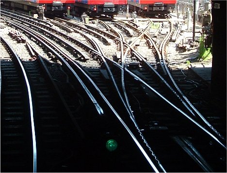
Conductor rails are necessarily absent for much of this 4-way turnout, with a consequent potential for 'gapping'. All three sidings (sidings 23, 24 and 25, at Farringdon) are signalled and tripstopped and fitted with trap switches. The green aspect in the right foreground is the eastbound station starter signal A225. 19 July 2005. Photo courtesy of and © Chris Cobley.
|
|
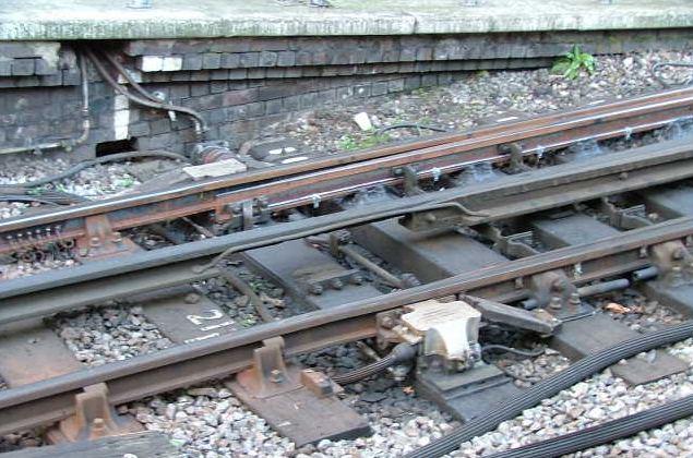
It is still the norm for the negative conductor rail to be continuous over the switches of bullhead turnouts, and it is current practice, known to be standard at least from 1945, to cut a 3'3" (nominal) long aperture, known as a 'fiddle cut' or simply 'fiddle', in the underside of the conductor rail, to clear operating and blade detector bars for turnout operating mechanisms mounted in the 4' way. To maintain good electrical conductivity along the conductor rail, 3/4" diameter copper wire bonds are fitted across the aperture on both sides of the conductor rail. The official drawing shows insulators supporting the rail either side of the fiddle.
Pneumatic chairlocks, on the side of the stockrails, are considered to have sufficient insulation not to require the fiddle, and the turnout operating mechanism itself is mounted in line with the axis of the switchblade operating rod, so it is unclear why the aperture is present in this particular example at Hammersmith (Metropolitan). It is unlikely this turnout was ever fitted with a 4' operating mechanism, as side-mounted ones are standard throughout this location. In this example, the negative conductor is unsupported over 5 timber bays. 8 March 2004. Photo courtesy James Moorhouse. |
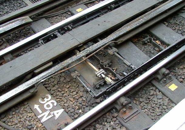
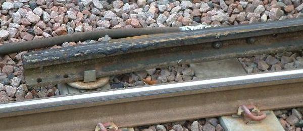
Another example of the underside aperture cut into the negative conductor rail. This aperture is considerably longer than the official nominal 3'3" length. The combined turnout and locking mechanism is mounted longitudinally with the track, and is covered by wooden planking. (This covering is allowed to be a maximum of 2" above the height of the running rails.) As is normal practice, the switchblades are insulated from each other, probably for track detection purposes, and the operating rod and locking and stretcher bars have insulating joints. Farringdon, 23 February 2004. Photo courtesy James Moorhouse.
|
|
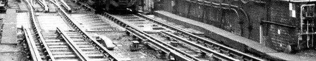
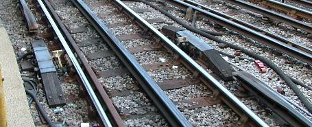
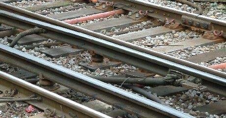
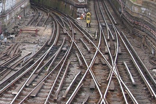
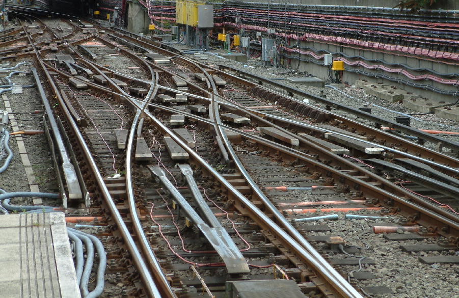
White City again, but this time looking east. The ramps themselves appear to be straight despite the comparatively sharp curvature of some of the track geometry. Out of gauge rails and cable conductor jumpers coexist here. Bullhead running rail throughout. The longitudinally-set turnout and locking mechanisms do not have any wooden covering. These mechanisms were specified to be laid in the 'straight' side of the turnout, but exceptions existed, as the picture (and that of Farringdon above) shows. 6 April 2003.
Photo reproduced with permission, © 2003 Richard Griffin, https://www.squarewheels.org.uk/ (Picture postscript: the crossover connection from the bottom right-hand to the top left-hand side of the picture was severed in the autumn of 2004, owing to concerns about derailments on sharply-curved turnout formations.) |
|
|
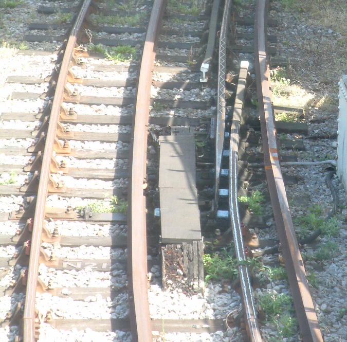
It is normal for positive conductor rails to be non-continuous over the length of divergent switches. This trap switch protecting one of Whitechapel's sidings is an exception, and the positive conductor rail is uncomfortably close to the end of the stock rail. The first timber of the switch is fitted with a stretcher bar (note the slide chair on its left-hand side), to keep the running rail gauge correct at the tip of the switch blade. The welded-on 'zigzag strip' on the switch rail aids track detection.
|
|
|
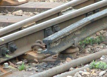
The old order changes. With bullhead running rail practice, negative conductor rails are usually continuous over the top of switchblade stretcher and detection and operating bars. The actuating and locking mechanisms on standard flatbottom running rail turnouts, even those used only in the trailing direction, have negated the presence of the negative conductor over the length of the switch, resulting in the complete segregation of the closure ramps, as shown on the left at the north end of Leytonstone. 23 June 2000. This segregrated style is now the modern norm on LT. Track renewal is a regular and ongoing process on LT, and segregated ramps can be increasingly found on bullhead running rail turnouts. Modern steel ramps are all fabricated, with portions of steel plate welded on top of ground-down conductor rail section, thereby avoiding the previous vertical butt weld between conductor rail and a ramp.
Below, the shortage of space in the station throat at Stratford (Jubilee) has led to the adoption of an unusual 'joined at the end' style of closure ramps on the scissors crossover. Interestingly, the straight routes between the turnouts of the scissors are not fitted with negative rail. There is even less provision for negative rail in the double junction at the top of the picture. Regardless of the negative rail provision, there is no skimping on negative shoe wooden slipper blocks. The flatbottom running rail geometry on the scissors is something of a showpiece, with cast crossings throughout, and modern style milled checkrails fitted with heavy-duty chairs. Picture taken on 12 August 2008. Both pictures courtesy of and © Ted Scannell. |
|
|
|
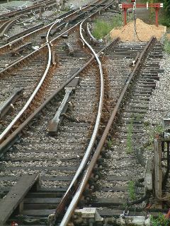
An overhead view of the bullhead scissors crossover at a verdant Upminster, 20 July 2005, showing segregated negative splices throughout. The blades on the trailing turnout at the top left are spring-loaded. Picture courtesy of and © Ted Scannell.
|
|
© Russ Elliott
(draft) first issued 16 November 2003
updated 18 November 2003: Southern standard insulator drawing added; typo on spacing of insulators diagram corrected; packing perimeter added to LT insulator diagram, together with improved shape of shed on the LT 4th-rail insulator; notes on packing clarified
updated 26 November 2003: note on conductor rail sizes added
updated 27 November 2003: flatbottom conductor rail footwidths clarified
updated 28 November 2003: out of gauge conductor rails section added
updated 30 November 2003: North Harrow, Lillie Bridge and White City west photographs added
updated 1 December 2003: insulator placing about 3rd rail fishplates clarified
updated 2 December 2003: further commentary on North Harrow picture added
updated 13 December 2003: 4mm scale model ramp pictures added
updated 25 January 2004: new sections for safety blocks and fishplates added, together with ASC details; Canterbury, Ascot, Hammersmith, White City east, Wood Lane, Barking, Leytonstone, Snaresbrook, Stratford, West Hampstead and Worting Junction pictures added.
updated 26 January 2004: length of long model fabricated ramp added
updated 29 January 2004: location of Southern electric insulator pics added
updated 2 February 2004: dates added for Canterbury, Ascot, White City east and Hammersmith pictures; better interface between top of insulator stalk and underside of shed on LT insulator drawing; Worting Junction shallow insulator picture replaced by Blackheath picture.
updated 3 February 2004: qualification on use of 150lb/yard conductor rail added.
updated 6 February 2004: tube tunnel conductor section weight clarified, side views added to LT insulator drawing and fixing bolts corrected to square.
updated 18 February 2004: single-sided protection boards noted; horizontal-base ramps for Southern noted; further notes on side-exit ramps added; minor editorial clarifications made.
updated 22 February 2004: note on insulators added; Amersham ramp picture added; dough mould resin insulator pic added; Bromley North and Lewisham pictures added; section on Southern side ramps revised.
updated 9 March 2004: safety block function clarified; Acton Town safety block picture added; Hammersmith (Metropolitan) and Farringdon turnout pictures added.
updated 11 March 2004: function of hook switches corrected and clarified.
updated 20 March 2004: LT conductor rail lengths specified; clarification of aperture on negative rail over LT turnouts.
updated 21 March 2004: safety block drawings added; insulator positions at ramps at turnout toes clarified; standard expansion gap and substation gap drawings added.
updated 22 March 2004: the term 'stirrup block' replaced by 'safety block'; positive rail overlap addressed, together with gap lengths.
updated 23 March 2004: relationship of chairlock mechanisms to negative splay fiddle cuts established.
updated 16 April 2004: Ewell East pics added to show Southern expansion gap and fair clip. Qualification on finishing of out of gauge rail added, together with qualification on placing of 4th rails through stations.
updated 1 May 2004: conductor rail positions for LT turnouts added; contents list added.
updated 15 May 2004: pics added to show exceptions to plain track insulator spacings.
updated 6 July 2004: historical overview added; Great Northern & City Railway details added; clarification of Central Line positive rail setting added.
updated 26 July 2004: fiddle cut drawing added.
updated 10 August 2004: LBSCR operating voltage corrected.
updated 5 September 2004: Rickmansworth bridge picture added.
updated 23 October 2004: clarification of W & CR operation by LSWR until 1907.
updated 13 November 2004: date of first LSWR operation added.
updated 23 December 2004: notes on LNWR London suburban electrification, plus LNWR insulator positioning, added.
updated 15 January 2005: 3rd rail overlap for Southern added.
updated 10 February 2005: LT trip stop mechanism added.
updated 13 February 2005: editorial: 'tripstop' replaced by 'trainstop' (sorry about that!). Query over 'clamplock' v 'chairlock' LT switchblade clamping mechanisms added. 'Fair clip' pairing noted.
updated 15 February 2005: Mitcham Junction pic added; Rickmansworth approach picture added; guidelines on termination of conductor rail at point and crossing work expanded; Wye diagram added.
updated 16 February 2005: location of Rickmansworth bridge corrected.
updated 18 February 2005: clarification of 'chairlock' (rather than 'clamplock') switchblade mechanisms fitted to LT lines.
updated 10 April 2005: Watford Junction and Buckhurst Hill pics added.
updated 18 April 2005: Volks Electric Railway, Giants Causeway, Liverpool Overhead Railway and Mersey Railway references added to historical overview. Rock Ferry, Ealing Common, Willesden Junction and Liverpool Overhead track pics added.
updated 3 May 2005: 3rd rail collector shoe positioning diagram added.
updated 14 August 2005: Southend Pier Railway reference added. EDT/instantaneous speed indicator rail added. Another Bromley North side ramp pic added. Canonbury horizontal-base flood ramps pic added.
updated 15 August 2005: Upminster cable feed pic added. Instantaneous speed indicator introduction date clarified. Upminster buffer stop pic added. Upminster out of gauge rail joiner pic added. Upminster scissors crossover pic added.
updated 1 October 2005: Ealing Common southward view added
updated 3 October 2005: Farringdon sidings pic added.
updated 21 December 2005: Edgware Road, Caledonian Road, and Mangapps Railway Museum pics added.
updated 5 March 2006: platform-adjacent positive conductor rail clarification for early District and Metropolitan practice.
updated 6 March 2006: details of conductor rail instantaneous speed indicators clarified.
updated 28 July 2007, to correct the description of the 319 shoegear
updated 23 July 2008, typical SR protection board bracket dimensions added
updated 24 July 2008, BR design rules for protection board lengths and support arrangements added
updated 20 August 2008, Cannon Street and new Whitechapel pictures added
updated 4 June 2009, LT shoegear tolerances added
(page code changed to html5 conformance 24 November 2011)
description of Worting Junction conductor rail bend corrected 20 March 2012
[page relocated after Virgin Media pulled the plug on their customer webspace services in June 2016]
Youtube video 'London Underground - Traction Current: Alive or Dead?' added 25 October 2016
Clarification of shapes of ends of out of gauge rail added 26 October 2016
clarification of initial placement of conductor rail on the Liverpool Overhead Railway added 27 October 2016
| Return to top of page | Safety, privacy and cookies |