Making a Cambrian SR 25-ton Pill Box brake van
by Ashley Pollard
Introduction (a ramble)It was the Saturday before Xmas, and I had innocently restarted my emails from the Yahoo Southern email list group that I normally just check the postings via the website. Someone had posted a comment about the Cambrian SR25t brake van kit being a perfectly good kit. To this I replied that my definition of what was perfectly good kit was obviously different to his, as there were three things wrong with the Cambrian kit, which I quoted as follows:
In the meantime I had come across the Geoff Kent book on building wagons, which proved to be a godsend as he had made one. He notes that it sat too low, the solebars were not deep enough, and him having had problems fitting pin-point bearings, requiring him to countersink them. So, I salvaged the bits I could from my first attempt, and bought a second kit to make-up. I restarted by building a new floor and shaving the flange off the solebars. Unfortunately, it was at this point that I had an accident with some MEK, spilling a bottle over the model's floor, which had a rather detrimental effect upon its progress. However, Cambrian sells spare sprues from their kits at shows. So I was able to procure another floor and set of solebars, but had become rather disheartened by events. So the kit languished in my ongoing projects box gathering dust. So there I was, the Saturday before Xmas, having posted my comments to which the replies were variants of are you sure? The truth was I thought I was, but the proof is in the pudding, so to speak. A dialogue then ensued, with people piping up that when they measured their model they got different dimensions than what someone else just posted. I found this is a perfectly understandable, if you take into account that the kits are produced using very basic injection moulding masters. After all, Cambrian are not Hornby/Bachmann etc. Strangely though, I found myself drawn back to my project and got out the forlorn parts from my project box and started to build it again. |
|
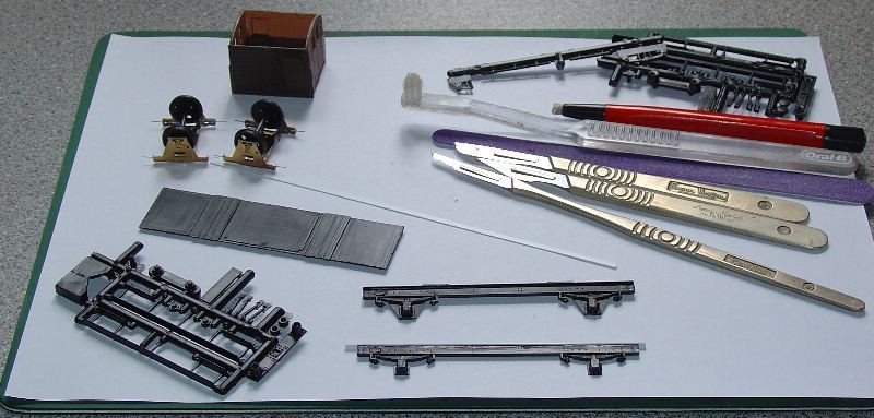
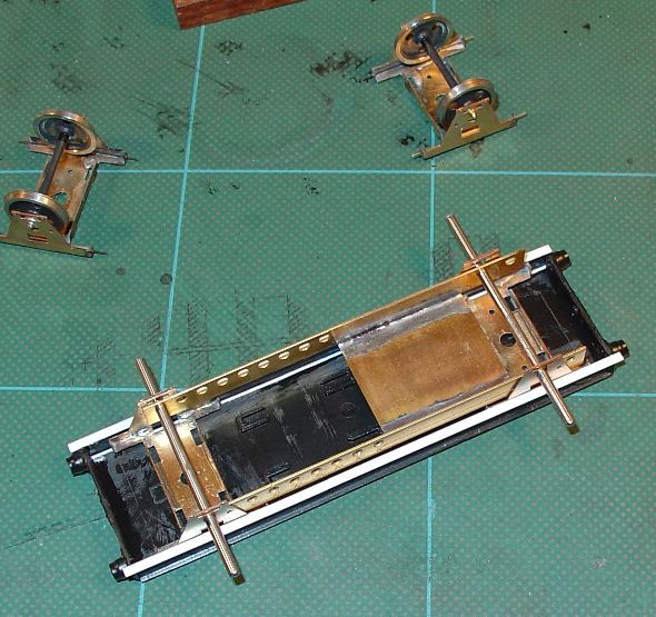
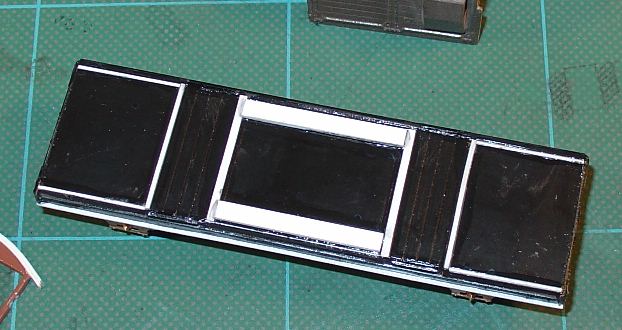
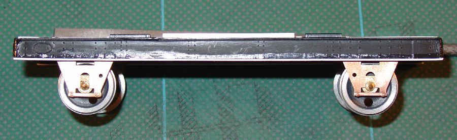
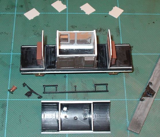
Underframe (floor, buffer beam and solebars)
To correct this I glued a 20 thou (0.5mm) microstrip on each side on the chamfer on the floor. However, this is not a strong joint, because there are no positive locking points. I therefore reinforced the joint between the floor and the solebar with some plastic strip. Even so this results in a floor that is about 0.25mm under width. I could have used thicker microstrip, 25 thou, but I would then have had to fabricate a new buffer beam, which I didn't want to do. Mostly because this would have made my an article on scratch-building a brake van, rather than building the Cambrian kit, as there would have been a cascade of other modifications that would have had to be made to the cabin of the brake van as well. 2 My kits solebars were 4.8mm deep, and should be 5mm. However, after shaving off the bottom flange, I had reduced the depth of the solebar to 4.5mm, so I glued a 20thou (0.5mm) piece of microstrip to the bottom of the solebar, which corrected this problem. Originally, on my first attempt I had shaved the top flange off the solebar, and there are merits for doing it this way, especially if you make a new floor. However, the caveat that this is an article on building the Cambrian kit, and not scratch-building apply. One other thing though, the kit is designed with a rebate for the cabin and veranda ends to sit in, and I therefore chose to fill this rebate in with microstrip. 3 To my surprise, I'm easily surprised, I then found that the W-irons were about 1mm too deep. Now as you can see, if you make the kit as supplied, then the fact that the W-irons make it sit tall, part way compensates for the fact that the cabin is too low. However, the model looks a little odd, and the buffer height may be wrong, depending on what wheels you choose. On closer examination it would appear that the extra depth is between the spring and the axlebox. As I was using Bill Bedford W-irons I chose to sand down the W-iron to remove it, and then split the spring from the axlebox. Problem solved. |
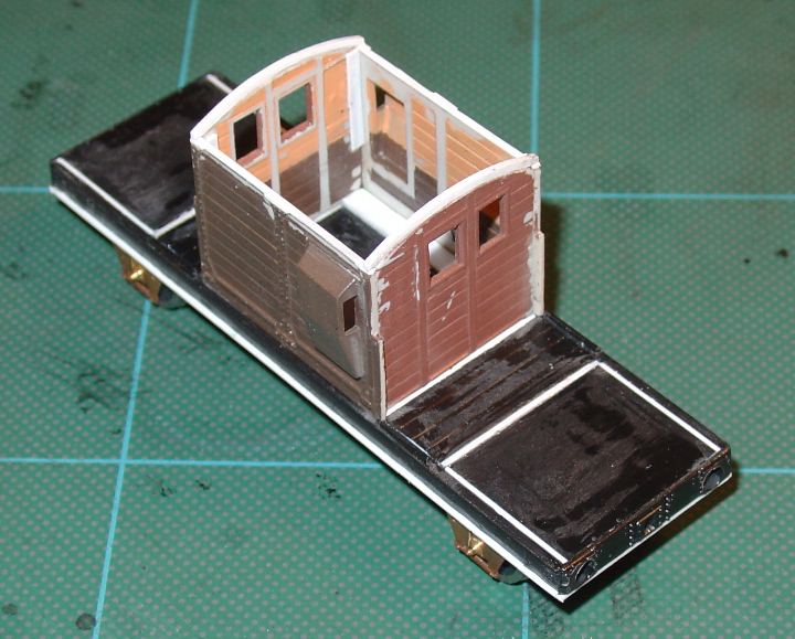
Superstructure (cabin, veranda ends, and roof)
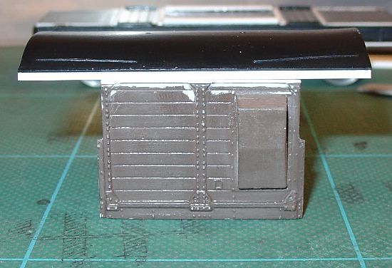 Body height As I discovered, once you correct the underframe and floor you still end up with a model that is under scale height. Even after removing the rebate in the floor, the brake van still sits 1.5mm too low. This seems to come from the combination of two things; the first is that side comes up 0.5mm under the height, and secondly that the angle iron that supports the roof is effectively missing.
Correcting this problem is confounded by the fact that the Cambrian kit allows you to make up one of several versions, with variations within each, of this SR brake van. The easiest to correct is the even plank version, which has a top plank that is too narrow. Fine for us, because you can add some 20thou (0.5mm) microstrip to the top of the cabin wall. This will correct this error quite nicely. Remember that you will want to use a piece of microstrip that is as wide as strapping on the model, so that you can carve back and fill in the missing iron work. However, the uneven plank version of the brake van top plank is the correct width. Therefore you might well want to consider adding the height to the bottom of the cabin wall moulding? I haven't made this variant yet, so haven't committed myself to a solution. |
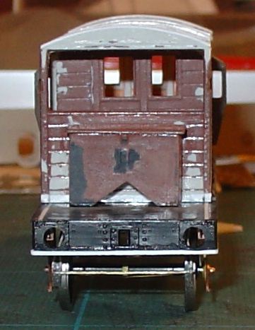
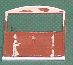 Veranda and cabin ends Once you've altered the sides this you will need to add some microstrip to the veranda and cabin ends, to raise their heights to match. They need to be treated slightly differently, as I found a slight discrepancy in the relationship between the windows and doors of the cabin versus the veranda opening between the kit and the plans and photographs I had.
For the veranda ends add 40thou (1mm) to the bottom of the moulding, and 20 thou (0.5mm) to top using microstrip. Again make sure that the microstrip you choose for the bottom is as wide as the iron strapping, so that you can carve and file to hide the joint. For the cabin ends you will want to add all the extra height to the top of the moulding. This will restore the correct relationship between the veranda opening and the windows in the cabin end wall, which Geoff Kent commented on in his article. Cabin width As supplied the cabin is 1mm too narrow, but I have not corrected this dimensional anomaly, because for me it would cross the line from building a kit, to becoming a scratch-build. However, while I've made no commitment, on reflection you could probably just widen the veranda ends by slicing them down the middle and splicing in a strip to make them the correct width. All a bit variable, depending on how wide your cut is etc. Alternatively, you could add file off the moulding of the iron strapping, and then put microstrip on each corner to rebuild the removed detail. You would probably add microstrip to the sides of the cabin ends, and carve the plan detail in. I leave this as a project for a later day. |
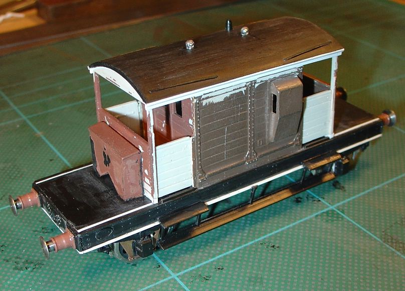
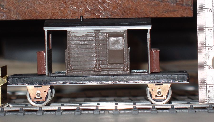
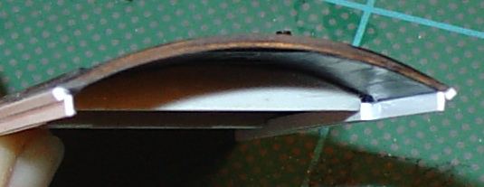 Roof width The roof is under scale width too, but I chose to widen it as it made correcting the absence of the roof supporting angle iron easier. Actually, I admit it, I bodged the roof. What I initially did was to build the angle iron support by attaching it to the roof. The roof has a sway back appearance, and I had problems with my first brake van after the roof became distorted when applying texture to it. I used spare parts from the kit to make some cross braces and attached a laminated angle iron made from microstrip to the underside of the roof. Thereby making it a stronger structure. It was at this point that I noticed that the overhang on the sides to said angle iron looked wrong. I then decided to add a strip to each side of the roof to correct the relationship, and serendipitously discovered that the roof was now the correct width.
|
Conclusion (a verdict)
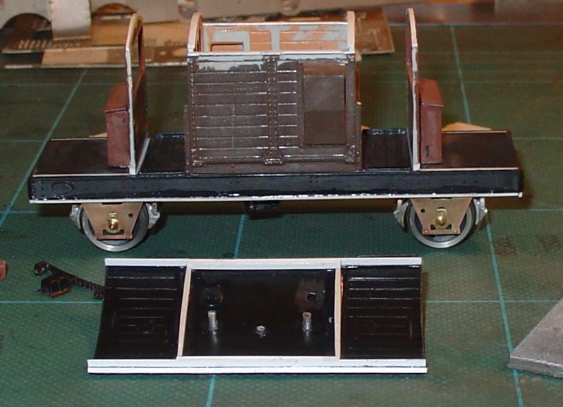
I am now near to completing my Cambrian SR25t Pill Box brake van kit, on the third attempt, which was all started from the throw away comment on an elist. As it is, I have spent 6 days of my spare Xmas time building this kit, and have yet to complete my model; still needing to add the brake gear (using some Bill Bedford brake etches), some sprung buffers, and couplings to finish it.
So the question remains, is it a perfectly good kit? My answer remains that your answer depends on your definition. I'm not attacking Cambrian, or have any intent to belittle this manufacturer who provides us with much needed wagons. My intention is merely to inform those who are interested in building a more accurate SR Pill Box what I found, so that they can answer this question for themselves.
I would also add that even with these corrections there are discrepancies between the model, the drawings and photographs of the prototypes. However, I would add that there are discrepancies in the manufacture of the prototypes, and variations in their assembly too.
I would also say that one needs a copy of OPC's An Illustrated History of Southern Wagons Volume 4, by Bixley, Blackburn, Chorley & King. I also can't recommend too highly the Wild Swan Publication, The 4mm Wagon Part 3, by Geoff Kent. Without these two books I would have missed the relationship between the various components that make up this kit.
|
|
© Ashley Pollard
October 2006
updated December 2007
updated 27 January 2008 to include pic with roof fitted
updated 28 February 2008 to add note from Cambrian Models
updated 1 July 2010 to delete reference to Ray Chorley's website
updated 15 January 2010 to add further update from Cambrian Models
| Return to top of page | Safety, privacy and cookies |