Red Panda BR clasp-braked underframe
by Simon Dunstall
Red Panda's BR 8-shoe clasp braked underframe can be found in their lowfit, sand wagon and shocvan kits, and is also available on its own. The additional components I use when detailing these underframes are replacement W-irons, buffers and drawgear. Other added details are built up from brass rod, brass strip and odd bits of plastic.
Brake gear assemblies
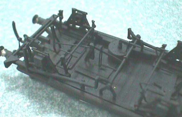
I use all of Red Panda's supplied parts, except for the cross shaft and vac cylinder actuator. As can be seen in the photo above, there's a lot of bits added as well.
The first job is usually construction of the pushrod assembly in the middle of the wagon. This is built up with brass rod and strip on top of a small piece of scrap brass. The dimensions of it are guessed, using wagon drawings given in An Illustrated History of BR Wagons Volume 1 as well as some other photos. I drew a large scale drawing, which is then used as a guide when constructing. The angles, lengths and sections used are chosen a bit arbitrarily, but the idea is simply to represent what is there.
The picture adjacent illustrates the individual parts that go into making this assembly. The dimensions relate to strip widths or rod diameters, and are rough estimates (I should go home and measure them). All the brass strip used is from Detail Associates, and is either 15 or 20 thou thick if I remember correctly.
The actuating rod connecting to the cross shaft is a piece of 0.040" wide strip that has a hole drilled through and is filed to shape in two stages. First, the tapered end (away from the hole) is shaped, while still attached to the strip stock. The part is soldered to another strip which will become the next rod in the assembly. After soldering, the other end of the actuating rod is filed to shape (this saves burnt fingers). Similar procedures are used for the other parts of the assembly – thinking ahead is a good idea. The last task is to attach a safety loop as shown in the photo, this being soldered to the scrap-brass baseplate. Arrange things so that the assembly can later on be set at the right height by use of some plastic-strip packing between it and the floor. Gluing a wide piece of 0.005" plastic to the baseplate first allows the assembly to be fitted to the plastic floor with solvent when the time comes (much easier than gluing it direct).
The next subassembly comprises two pairs of safety loops and another bit of the brake gear. There are two of these, one for each W-iron. The picture adjacent shows this subassembly. I use 0.020" rod for the safety loops and 0.040" wide rod, bent up to shape, for the brake gear piece. The brass used for the cross-shaped base can be more or less any section, as long as it isn't too wide. These subassemblies are then soldered to the W-irons, and bearings fitted to the W-irons at this point as well. The bottom part of the cross-shaped base doesn't need to stick out much, and in fact it can't be allowed to do so on a rocking W-iron, as it will foul the rocking tabs.
Wide pads of 0.005" plastic are then stuck to the W-irons, underneath where the brake shoes will go. At that same time (if using three point suspension), similar pads are stuck to the bottom of the fixed W-iron and to the bottom of the rocker of the other W-iron. The shoes are shaped and drilled at the back, then glued to the pads. When glue has dried, and all the rest of the brake gear is fitted (incl. cross shaft etc.), tie rods are put in between the shoes – these are rod of some description. The W-irons, complete with all their brake gear, can then be fitted to the wagon with solvent, using extra plastic sheet packing pads if required.
Cross shaft and brake levers
Once the W-irons are on, the cross shaft, brake levers and vac cylinder are installed. First brake levers are prepared, with a 0.030" hole drilled through where they connect to the cross shaft. A vacuum cylinder actuator is made up out of scrap, and holes drilled in the vac cylinder for a safety loop to be added later. 0.030"-ish holes are drilled in the apex of the vee hangers on the solebar, and then a piece of 0.030"-ish brass rod selected for a cross shaft and cut to size. With all these bits prepared, the various bits are threaded onto the cross shaft, and the cross shaft threaded into the vee hanger holes (the bits being the vac cylinder actuator, brake gear subassembly and the two brake levers). The cross shaft is glued in position, and small circles of plastic glued over the holes in the vee hangers. Finally, the base of the centre brake gear subassembly is glued to the floor, after being packed as required.
With this method of attaching the brake levers, there's no chance of them falling off! Also, if you attach the tie rods between the brake shoes before this point, they will get in the way of the push rod of the centre brake gear subassembly. This push rod is often best trimmed to size at this assembly stage.
Headstocks, solebars and floor
Of course, the solebars need to be prepared and fixed to the floor before the brakes go in! With reference to the photo, you can see that I haven't used the floor provided with the shocvan kit, as it would cramp the between-solebars area.
The solebars have had the plastic W-irons filed away as usual, and have had some cosmetic detail rearranged to suit the shock-gear fitted vehicle (a diagram 1/218 van). Careful filing away of the W-irons allows a near-invisible compensation arrangement on Red Panda-underframed vehicles. File the solebar from the rear, with spring and axlebox still attached, until the W-iron is wafer thin. The outer bits of W-iron will then pop off under slight pressure. Cut away the rest of the W-iron, between the solebar and spring, and then very carefully snap out the spring and axlebox assembly. A small nick with a scalpel may be necessary here. There will result almost no gap between spring shoe and spring. A tiny bit of filing gives enough clearance, and the spring plus axlebox assembly can slide up and down between the shoes.
Best results are obtained by attaching the spring and axlebox assemblies to the W-irons before the latter are fitted to the vehicle. Using this method, the presence of compensation is almost imperceptible (until you drive the wagon over a bump) because it is nearly impossible to see the cuts.
The buffers on the underframe in the photo are Dowty-pattern, obtained from MJT. These can be bought as sprung buffers or dumb buffers; these examples were dumb but have now been sprung! BR vehicles with this pattern underframe could also be found with Duplex buffers or various types of Oleos, and maybe ordinary spindle buffers too. The vacuum pipe is a bit of 0.020" brass wound with fuse wire. There's a bracket for clipping the end of the pipe into, this made up from thin brass strip and a small thin circle of rod cut from K&S 1/32" tube using a cutoff disk in a mini-drill (sounds fiddly, but is actually quick and easy). I don't know which headstock it is, but one of them on this wagon is made up from brass, using a section cut from K&S rectangular section tube. Using a brass headstock allowed the buffers to be soldered on, as well as the drawgear, vac-pipe and vac-pipe bracket, but was harder to fit onto the rest of the vehicle and took more time to make. Much of a muchness really; I definitely cannot say I will always substitute these for the plastic headstocks (which the other end has, and which my four other BR 8-shoed vehicles have).
Finished result
Although many of the brake gear parts are just representational in shape, they clutter up the underframe enough to make the result a lot more convincing than before. And, although some work is needed for this detailing, it doesn't take that much time to do.
© Simon Dunstall
March 1999
| Return to top of page | Safety, privacy and cookies |