.gif) |
|
| this page hosted by | |
Scalefour Digest 1.2
Issue 2, December 1998
P4 Track and Wheel Standards
by Russ Elliott
Contents
Introduction
General comments on P4 standards
Table 1 Recommended P4 track and wheel standards, 4' 8½", 5' 3" and 7' 0¼" nominal prototype gauges
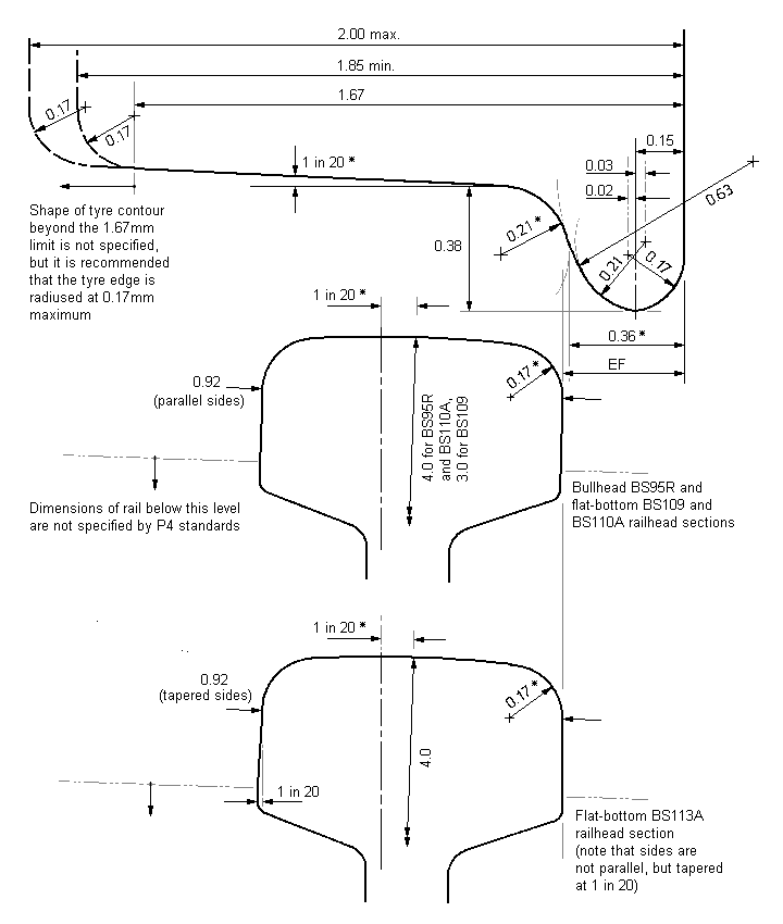
Figure 1 P4 tyre profile and railhead contours
Annexes:
Recommended dimensions at turnout switches
Use of gauge widening
Use of 4mm scale equivalent dimensions (4' 8½" gauge)
Prototype track and wheel dimensions (for 4' 8½" gauge)
Technical derivation of P4 track and wheel standards
Acknowledgements The P4 standard track and wheel dimensions given in this section of the Digest were produced by the members of the Model Railway Study Group (MRSG) in the mid-1960s. The railhead sections and tyre contour drawings are based, with permission, on the original Protofour track and wheel drawings made by Joe Brook Smith.
Introduction
This revision in the presentation of the P4 track and wheel standards has been produced:
- to provide information for existing and potential manufacturers who wish to produce components to P4 standards (the original presentation of the standards having been drawn up with only one manufacturer in mind);
- to provide information to modellers on the derivation, purpose and operation of the standards.
It is emphasised that much of the material given in this section of the Digest, particularly that shown in figure 1, is directed primarily at existing and prospective manufacturers of P4 components. For the modeller, the available construction gauges and rail components should result in correctly constructed P4 track without the need to measure anything or the need to refer to the standards, but it is hoped that the information regarding the derivation and operation of the P4 standards will give both modellers and manufacturers some of the founding principles behind the standards, and will therefore be of interest.
In the derivation of the standards, manufacturing tolerances, including the effect of the possible build-up of tolerances on other dimensions, have been taken into account, but the Society welcomes any comments from manufacturers in the application of the standards.
The P4 recommended track and wheel standards are given in table 1, and are conditional on the use of the railhead contour(s) and tyre profile shown in figure 1.
Annexes to this section of the Digest contain information on:
- recommended dimensions at turnout switches
- use of gauge widening
- use of 4mm scale equivalent dimensions
- protototype track and wheel dimensions (for 4' 8½" gauge)
- technical derivation of P4 track and wheel standards
Note With the exception of figure 1, the drawings are not to scale.
General comments on P4 standards
Some members, especially new ones, become rather concerned at the prospect of having to work to two places of decimals of a millimetre. The Society would like to point out the following:
| 1 | Any measurement is not necessarily less exact even though it is not expressed to two places of decimals. The 'OO' and 'HO' gauge of 16.5mm should be exactly that, so is no more or less precise than the P4 gauge of 18.83mm. |
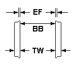
| 2 | The construction gauges ensure that you get the dimensions correct when you are constructing track without the need to measure anything; the wheels supplied already conform to P4 standard dimensions, although it is recommended that the wheel back-to-back dimension (BB) should be checked for all wheelsets. |
| 3 | The prototype dimensions from which the P4 values were calculated are only nominal, as continued wear on track and wheels means their profiles soon differ from the standards conceived. The same wear is unlikely to take place on your layout but, in extreme cases, although you may have started with the correct dimensions, your wheels and track may deviate from them with continued use. |
| 4 | It is not unusual to hear or read remarks to the effect that there is nothing inherently better to be gained by using a gauge of 18.83mm (or the equivalents in the cases of 5' 3" and 7 '0¼" prototype gauges) for 4mm scale modelling. This is, in fact, a part truth, but applicable only to plain track. The important thing to remember is, when using components to P4 standards, you can be sure, in those respects that matter, all such components are correctly designed to give optimum results notionally on plain track but also through all pointwork, however complex. The same results could be, and occasionally are, achieved in EM and OO by modellers with sufficient skill to modify the parts they buy to the same consistency and accuracy as is built into components complying with P4 standards. |
| Table 1 Recommended P4 track and wheel standards, 4' 8½", 5' 3" and 7' 0¼" nominal prototype gauges | |||||||||
| Dimension All P4 dimensions are in millimetres |
4' 8½" gauge | 5' 3" gauge | 7' 0¼" gauge | ||||||
| min. | max. | min. | max. | min. | max. | ||||

|
|
18.83* | see GW | 21.00* | see GW | 28.08* | see GW | ||
|
- | 0.22 | - | 0.22 | - | 0.22 | |||
|
18.15* | 18.20 | 20.32* | 20.37 | 27.40* | 27.45 | |||
|
0.65 | 0.68* | 0.65 | 0.68* | 0.65 | 0.68* | |||
|
- | 17.47* | - | 19.64* | - | 26.72* | |||
 |
|
0.35 | 0.40 | 0.35 | 0.40 | 0.35 | 0.40 | ||
|
17.67* | 17.75 (see note 3) |
19.84* | 19.92 | 26.92* | 27.00 | |||
|
1.85 | 2.00 | 1.85 | 2.00 | 1.85 | 2.00 | |||
|
 |
|
| Notes: | |
| 1 | Any deviation from the dimensions marked * will alter the effective flange dimension (EF) from the P4 standard. Deviation from any flange or railhead dimension may adversely affect performance. |
| 2 | The tyre profile is based on BS 276 contour A. |
| 3 | All dimensions are in millimetres. |
| 4 | The tolerances on any contour tools used for the production of tyres or rail are recommended to be:
± 0.0125mm, for all flange dimensions (with the exception of the tyre front edge radius); ± 0.025mm, for railhead dimensions. |
| Figure 1 P4 tyre profile and railhead contours | |
Annexes
Recommended dimensions at turnout switches
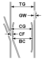
The following dimensions should be observed at turnout switches:

Use of gauge widening
Gauge widening should not be applied to any sections of pointwork where CG, CF or BC dimensions are specified.
Where applied to non-pointwork curves, prototype gauge widening at 10 chains radius is 0.25", at 7 chains radius is 0.5", and at 5½ chains radius is 0.75" maximum. (In 4mm scale, 1 chain is equal to 264mm, or approximately 10½".) In P4, where BBmax is less than the 4mm scale equivalent, and where adequate sideplay can usually be given to inner axles, gauge widening should not be necessary unless using long-wheelbase stock around sharp curves.
Where required, check rails should be set from the outer rail of a curve, using a CG gauge (in the same manner as the CG gauge is used in turnout construction), and gauge widening should be applied only to the inner running rail if wheelsets are still found to be binding.
Use of 4mm scale equivalent dimensions (4' 8½" gauge)
For a number of reasons, some of the P4 recommended dimensions are not exact scaled-down equivalents of the prototype dimensions, and most modellers use the recommended P4 dimensions as published, with wheels, track components and construction gauges conforming to these standard dimensions. The exact scaled-down dimensions differing from the P4 recommended values are:
| CG | Check gauge | 18.25mm |
| CF | Crossing flangeway | 0.58mm |
| BC | Between checks | 17.67mm |
| BB | Wheel back-to-back | 17.87mm |
Wheelsets built accurately to P4 dimensions will not run through exact-scale pointwork, but 4mm scale equivalent wheelsets (with the increased BB) will run through pointwork built to P4 recommended dimensions. It is emphasised that the Society recommends only the P4 dimensions, whilst recognising that more experienced modellers may choose to use the 4mm scale equivalent dimensions.
The P4 recommended BB dimension is specified in order to allow vehicles with a rigid wheelbase of more than 2 axles to negotiate turnouts and curves appreciably sharper than the prototype equivalents. The 4mm scale equivalent dimensions are used by some modellers to:
- reduce sideplay between wheels and track;
- improve the functioning of check rails in obtuse ('K') crossings and to improve the running characteristics of wheelsets through certain configurations of turnouts.
The use of the 4mm scale equivalent BB dimension may be found to be beneficial for all 4-wheeled vehicles, and for vehicles of greater than 4 wheels where adequate sideplay can be introduced on the inner axle(s). In this sense, the 4mm scale equivalent BB dimension should not be regarded as incompatible with other P4 recommended values, since, as stated previously, the 4mm scale equivalent BB wheelsets will run through pointwork conforming to P4 dimensions. It should however be noted that the 4mm scale equivalent BB may result in the overall wheelset width exceeding very slightly the nominal prototype equivalent maximum of approximately 21.7mm; Society compensation components are designed to cater for this very marginal difference.
In practice, the only difference required to implement the 4mm scale equivalent dimensions is a slight adjustment of the BB value and crossing flangeway (CF) setting.
Prototype track and wheel dimensions (for 4'8½" gauge)
For information, and comparison with the P4 values, the prototype 4' 8½" track and wheel dimensions and their 4mm scale equivalents are given in table 2.
| Table 2 Prototype track and wheel dimensions (for 4' 8½" gauge) | ||||||||||||||
| Dimension | Prototype | 4mm scale equivalent | ||||||||||||
|
4' 8½" | 18.83mm | ||||||||||||
|
¾" (maximum at 5½ chains radius) | 0.25mm | ||||||||||||
|
4' 6¾" | 18.25mm | ||||||||||||
|
1¾" | 0.58mm | ||||||||||||
|
4' 5" | 17.67mm | ||||||||||||
|
1⅛" | 0.38mm | ||||||||||||
|
4' 5 19⁄32" minimum 4' 5 21⁄32" maximum |
17.87mm 17.89mm |
||||||||||||
|
5" minimum, 6½" maximum (see note 1) |
1.67mm 2.17mm |
||||||||||||
| Tyre contour | Various (see note 2) | |||||||||||||
|
||||||||||||||
Technical derivation of P4 track and wheel standards
 Tyre and railhead contours as per figure 1
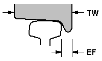
The most important single factor in ensuring reliable P4 operation is the maintenance of the correct tyre and railhead contours, and the successful use of the P4 track and wheel standards is conditional on the use of the scaled-down equivalents of these contours, as given in figure 1. From these contours is derived the effective flange thickness dimension (EF), which is the distance between the rail running face and the back face of the wheel flange when the front of the flange is in contact with the rail, i.e. when the flange root radius meets the radius at the side of the railhead; any further movement of the wheel toward the rail will cause the wheel to ride up and loose contact at the tread. The EF dimension replaces the complex actual dimensions of the flange in the compilation of the P4 track standards. The P4 value for EF is specified as 0.35mm minimum to 0.40mm maximum, and is equivalent to the corresponding nominal 1.125" EF of the prototype flange dimensions.
Many of the dimensions given in table 1 are interrelated, and the following conditions, whose basis applies equally to the prototype, have been used in the formulation of P4 standards.
| Key to diagrams | V = crossing vee W = wing rail C = check rail R = running/stock rail |
TG = track gauge CG = check gauge CF = crossing flangeway BC = between checks EF = effective flange thickness BB = wheel back-to-back TW = tyre width |
| Note The following diagrams are representational, and are not to scale. | ||
|
||
|
||
|
||
|
||
|
||
|
||
|
end
© Russ Elliott 1998
| Return to top of page | Safety, privacy and cookies |


