Equalising sprung bogie
|
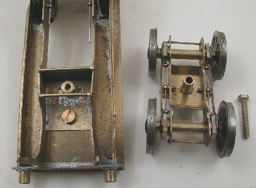
Top view – the bogie has a slightly elongated slot to allow the bogie some sideways translation relative to the mainframes. This is controlled by the coil springs underneath.
|


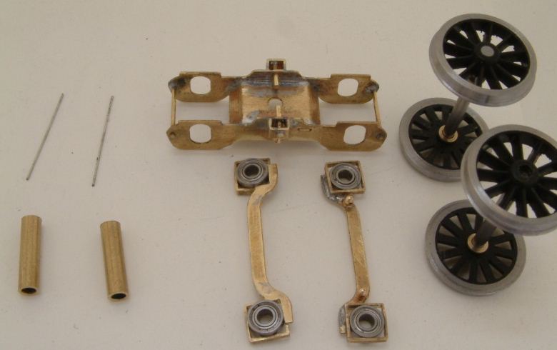
Components: the ballraces are trapped within slices of square-section tubing. The equalising beams and frame are from a London Road Models Midland Spinner kit. Wheels are Sharman, and the springs (guitar string) are carried by Markits 1.5mm diameter 1mm pitch 'original' type handrail knobs, two being attached to each end of each beam, and another attached to the midpoint of each side of the bogie frame. The axle tubes are a loose fit on the axles, and the axle tube length keeps the equalising beams at the correct distance.
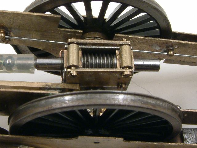
This isn't on the bogie, but shows the 40:1 gearbox on the main loco driver. The gearbox is an 'old-style' Exactoscale, with fabricated extra sideplates, and original spacers replaced with tube and 14BA screws. Since the input shaft is underneath the axle in this model, this is for added security, as well as improving the ease of assembly and disassembly.
The springs on the driver are 0.020", over a 33mm span length.
© Ted Scannell and Russ Elliott
first published June 2005
issue 2, 29 January 2006
link to non-ballrace page added 4 December 2008
| Return to top of page | Safety, privacy and cookies |