The result of putting the model under a scanner – the slightly odd angles of the w-irons are attributable (mostly) to gravity and the wagon's suspension.
LNER 12T ply-sided Fruit Van
by Simon Dunstall
Building and detailing the Parkside LNER 12T ply-sided Fruit Van (LNER Diagram 187 or BR Diagram 1/232) involves a reasonable amount of work, but nothing out of the ordinary. Cleaning up the mouldings does take some time, due to a fair bit of flash being present (especially on the sides). Also, some repairs may be necessary at the top of the sides above the doors – Parkside seem to chop the mouldings off sprues in a pretty careless manner sometimes.
The good thing about building older-style Parkside-Dundas kits is that there is usually very little removal of detail required (compare with a Ratio Toad for example!). For example, there are no chalkboards on the fruit van sides or rainstrips on the roof – you'll get no complaint from me about that. The time it takes to add details like this is relatively enjoyable, whereas when I have to remove them and put them somewhere else I get narky.
Adding various bits and pieces to a van is straightforward work, particularly if you use Geoff Kent's wagon books as a guide. Geoff Gamble's Railways in Profile 3 – British Railways Vans (Cheona Publishing) contains a number of photos of LNER Fruit Vans, including ply-sided ones, and armed with these books I didn't need to refer to other prototype information. My model is essentially E277892 (Plate 91 in Cheona's Van Book). Photos of other wagons (NE285714, Plate 35 and B755165, Plate 92) also came in very handy during building.
Roof, sides and ends
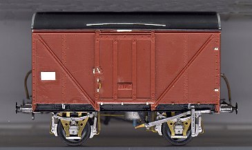
 Under a scanner again... the model is sitting on its end – this explains the odd looking screw coupling!
The roof needed (short-curved) rainstrips and end strapping added, the latter receiving fasteners of some sort along its length (see B755165). The strips were cut from 0.005" plastic, as per usual. The sides needed chalkboards (left-hand end) and door stops (right-hand end), and I also improved the look of the door lock. Each of these jobs consumed 0.005" and 0.010" plastic sheet, chopped into the right shapes and sizes. In more-or-less the usual manner the door handle was modelled by embedding 0.012" brass rod, bent up into a U-shaped piece, into location and appending small rectangles of 0.005" styrene at either end, tiny cubes being added last to represent the securing bolts.
The only tricky job was the addition of the five door runners at the base of the each side. With the door closed there are three of these runners under the door and two runners to the right of the door. The latter runners I modelled by bending up 0.010" brass strip into a 10mm+2mm+5mm J-shape, grinding the 5mm edge down to about 1mm high, and epoxying a rectangular piece of 0.005" plastic inside the J, attached to the 10mm section. One the epoxy had set the runner can be fixed to the inside of the side with solvent – this being a 'safer and better' way of attaching it. The door runners under the (closed) door were modelled with collections of small plastic rectangles.
On the ends vacuum pipes, drawgear, lamp irons, and buffers are the main items to be added. On at least some fruit vans there seems also to be a mysterious rectangle, about 6" by 1', spanning the bottom 2 corrugations (sorry, vents!) and located just off the wagon centreline. What they are I do not know, but it seems that E277892 had them. The vacuum pipes I knocked up out of guitar string, solder, 0.012" brass wire and 0.010" brass strip. The buffers are ABS RCH fitted-stock buffers, drilled out to accept MJT sprung heads. This pattern of buffer does not seem completely correct for E277892, but close enough for me. I remember having to file the end of the headstock to shape before fitting the ends and sides together – this end becoming the lower part of the corner strapping.
Solebars and brakes
I elected to chop off the w-irons off the solebar moulding below the bottom of the solebar, and fit MJT 5-leaf (pressed steel shoe) springs. The brakegear is a combination of ABS brake shoes and levers (from their LNER fitted 10' wheelbase pack), Parkside's clutch rod (is that what you call it?) for between the two V-hangers, 0.015" brass wire for the various safety loops and push rods, 0.022" for the cross-shafts, and brass strip for the actuator from the vacuum cylinder, the crank off the cross-shaft (terminology troubles again!) and the two link assemblies near the vehicle ends that allow the push rods to engage the brake shoes (for these, see the photo of the ends). The safety loop around the clutch rod was made by first filing a flat surface on some 0.012" rod.
The vacuum cylinder is from the ABS pack, and I chose to thread some insulation from some thin electrical cable onto the 0.012" actuator rod to model the rubber fitting found on the prototype. There's also a representation of the pipe connecting the vacuum cylinder to the vacuum pipe (gilding the lily just a little bit!). The brake shoes and the link assemblies, as well as the axleboxes, have been soldered to the w-irons, which are Scalefour Society BR pattern. For representing the BR split-type axleboxes I took MJT RCH axleboxes, filled in the top of the slot with a blob of solder, and then filed them to a better shape. The vehicle is compensated using a method devised by Ted Scannell, but nowadays I'd opt for Bill Bedford sprung W-irons. The axleboxes and springs are not joined, this allowing the w-irons to move.
A body-to-solebar bracket was required (on the sides) at the lower ends of each of the diagonal braces, and others were needed in the vicinity of the vertical straps on the sides. I added four triangular bits of 0.005" styrene to represent the strengthening pieces joining between the solebars and headstocks (these being attached to the lower flange of the solebar). Lastly, screw couplings from the MJT BR W-iron etched were knocked up and fitted.
© Simon Dunstall
March 1999
| Return to top of page | Safety, privacy and cookies |