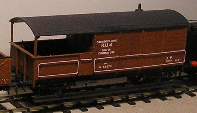
I would normally use HMRS transfers, but needed some custom transfers for other models anyway, so these transfers are also from homemade artwork, and printed by Brunel Models. The model is now awaiting weathering and glazing.
The near-completed toad, after about 15(?) hours of work. As yet unattached, the roof is struggling to stay on, but the inside of the verandah will be painted first before the roof is glued. A few bits are wonky – never mind. The solder joints in the handrails betray that they are bent up from one piece of rod (I used a length of thick K&S brass as a gauge for the handrails, its width was spot-on). The rivets that needed to be added to the sides can just be made out, as can some of the unsightly scratches on the solebar. Dirt can fix anything though. Looking closely, I need to address the join between the solebars and the headstock. Sandpipes and some running-gear details are yet to be added.
|
GWR 'Toad' brake van
building an AA20 using the Ratio kit
model and description by Simon Dunstall, prototype pictures by Bryan Johnson
I suspect that the GWR Toads, of one diagram or another, have been discussed in the modelling press a number of times over the years. Not being a great consumer of modelling mags I've got no idea when or where, except that Mike Clutterbuck talks about building Ratio toads in the BRMA's journal The Clearing House (Number 64?). In any case, building a toad is much like building any other item of rolling stock; get a few good pictures, and maybe a drawing or two, and start sticking bits of plastic and brass together...
With the arrival of Cheona's Brake Vans and Cattle Wagons the first requirement is met well. Within the twenty or so photographs there's ample information, particularly if building a later diagrams. I chose to build a model of W68870, an AA20 van which was through-piped by BR at some point before 1962 (the date of the photograph). I also dug out my copy of the Titfield Thunderbolt, putting the video on slow-mo in appropriate spots where the Toad took centre stage. I don't suppose there was too much extra information available from the film (although it appeared that the underside of the roof was painted cream – possibly only for filming purposes). On the other hand, if building a 14xx there is a lot of useful material there. On the diagrams side, Russ Elliott was kind enough to send me photocopies from a couple of GW wagon books, and these came in handy for the placement of items and working out the dimensions of the running boards.
Building the Toad started off with the inevitable – taking off moulded detail. The handrails, lamp irons, chimney and axleboxes were removed. The latter I replaced later with some BR split type axleboxes filed to an approximate shape from MJT RCH axleboxes. Some solebar detail also came off, although while I can see the scratches I left, I can't figure out what was there in the beginning. The headstocks were cleaned up to accept replacement buffers. I reduced the size of the locating lugs on verandah sides at this stage as well. Although I dislike the detail-removing process – and a Ratio toad is quite demanding in this respect – the job wasn't so bad, and after about three hours in front of the TV I think I'd finished. I believe I could have been a bit cleaner, but my patience for such tasks is limited.
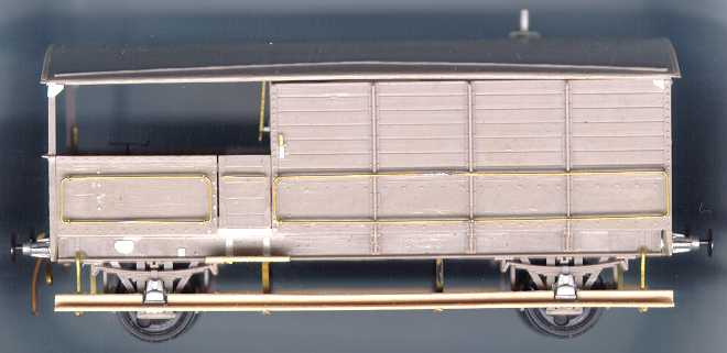
Nothing too unusual happened in the 'putting together stage'. I did have to play about with the size and shape of the doors. In the photo of the near-completed model you can see that I used some 30-thou plastic underneath the door, this lying flush with the rest of the side, and adjusted the door height to suit. As far as I can remember, this was done because in the original ratio design the 'floor' underneath the door is moulded as part of the door – this leads to the door appearing to stretch all the way to the top of the solebar.
For compensation, I used an MJT internal-bearing rocker on each end, and filled the gap betwen the rocker and the support with slices of appropriately-chosen foam. Sort of a 'foam-bag' suspension... well, whatever, it works, but doesn't roll too well owing to friction at the bearings. Talking of the bearings, the holes were cut through at the bottom end to form an open-ended slot, and normal pin-point axles were then inserted. The (empty) bearing-holes in the solebars stop the wheelsets from falling out when the vehicle is picked up. This dodge should reduce the friction at the bearings, saved me from having to file axles and remove wheels, and makes for easier wheelset exchange if and when that is required (e.g. when painting). I'm sure there's better schemes, but this one is okay.
Nowadays, I would use some Bill Bedford sprung W-irons instead.
There's many items that can be added to the model, and often many ways to model the same item you're adding. Starting with the buffers, these are ABS 4-rib RCH buffers with collars, drilled out and sprung with MJT heads, and match well those on W68870. Lamp irons (4 of them) were built as usual, using round brass rod filed flat, bent 90 degrees, inserted into a hole and appended with a rectangle of 10-thou plastic for the 'bolted on bit'. Vac pipes and brake rodding are guitar string and brass rod. Sandpipes were bent up from brass rod and attached in pairs to transverse stretchers, which fortuitously are in the right spot when glued to the lugs Ratio provided at each side of the axles. The footboards are, just to be different, actually constructed from wood – made by a US company under the name 'Scale Lumber' I think. The available sizes were not exactly what was needed, but a knife fixed that, and there's no problem painting them to look like wood...
 The running-board supports are brass rod (outer ends) and a soldered-up brass rod-and-strip combination for the L-section centre supports. The brass strip is about 0.25mm thickness. Note that the orientation of the L seems not to have been standardised, but on W68870 all L's have one flange facing outwards and the other towards the lengthwise-centre of the van. The two L-supports per side are soldered to each end of a piece of flat brass strip, about 2mm wide and 25mm long. A simlar length of 15 thou plastic was epoxied to the outside of this stretcher, and the whole thing mek-ed to the inner face of the solebar. Before the gluing, one of the stepboard supports (under the door) also needs to be attached to the stretcher, on the opposite side to the L-support and directly in line with it. Yes, it is easier to look at the picture. Note that the two flanges of the L should be about the same width, unlike in my sketch. For the other stepboard support flat strip is bent into a small L-shape and 'hooks' behind the solebar, attachment aided by another strip soldered across the back of it. Lastly, the outer running board supports fit into holes drilled in the solebar.
 Handrails were another area of trickyness. On the real thing there are four supports on the verandah-side handrails and ten on the cabin-side handrails, six of which are welded/rivetted to the outside frame members. On the model I couldn't see any way to model the latter six brackets, and settled for epoxy. For the remaining (outer) supports, I drilled 20 thou holes in (approx) 0.25 by 1.5 mm brass strip and 'sculptured' out the shape of the support using a cutting disc in a mini-drill, as shown in the picture. After making sixteen of these (well, more like three dozen), four each were threaded onto each handrail, the handrail soldered up, and the assembly stuck into the side of the van with epoxy. Note that later vans have a different type of handrail bracket. The one-piece handrails are not easy to solder reliably together, and some hair-raising spot repairs have been required after other building steps have used a bit too much force. I dread to think what will happen if a loco ploughs straight into the side of a derailed toad and sends it flying to the floor. Other work on the sides involved adding rivets beside the door and on the outer verandah where the end of the sandboxes presumably are.
Inside the verandah is where most of the fun is. There's a number of things that can be done. I think I've done most of them, but probably not all. First there is the rear sandbox lever mounted on the cabin wall, an easy job. There's also rivets placed to match those on the outside of the verandah ends and sides... not everyone's cup of tea. Thinking ahead, you also should scribe planking onto the inside of the doors before they go on, and put planking on the floor. I opted to use strips of 5 thou plastic for the floorboards, this being more enjoyable for me than scribing (and a damn-site easier to do if, like me, you forget the planking when putting the model together). I also added bracing on the inside of the doors, with 5 thou plastic.

|
A view into the verandah of W68870. The bits of rod sticking into the cabin are from lamp irons and the rear sandbox lever. The vacuum control valve is top-left, and the brake wheel is centre-left. The bench between the sandboxes can be clearly seen, with the (vertical) sandbox lever being near the top (i.e. right) sandbox, and the actuating rod hugs the verandah end. The sprake holders should be placed on the wall close to the sandboxes, I believe, although this will make the area near the vacuum control valve a bit cluttered. The reinforcing triangles at the top of the verandah sides can be seen, with the lower one threatening to break off at the moment.
|
The 'thing' placed halfway up the inside of the side wall in the photo of B950592 (see prototype picture below) is, I'm told, a sprake holder (a sprake apparently is a chunk of wood that is placed in the holes of wagon wheels to stop the wagon from moving). I knocked two sprake holders up out of brass rod and strip, these are not shown in the model photo above. The brake wheel also is an assembly of brass rod, tube and wire in this case, as is the vacuum-control valve which sits near the right-hand sandbox. I used the sandboxes supplied by Ratio, and then built up the bench between them (on W68870) in various bits of plastic. Before fitting the sandboxes, I drilled holes to accept the brass rod used as part of the sandbox lever arrangement. This assembly is tweaked-up 20 thou rod, attacked as usual with a cutting disc to get a representative profile on the various bits.
The chimney on the roof was built using K&S aluminium tubing. The "Frankenstein's neck" looking bolts in it were secured by shoving a brass rod up the chimney, putting some wire into the holes drilled for the bolts, tinning the bits beforehand and then giving the lot a serve with the soldering iron. As far as I know, inside the chimney the brass rods have formed a T-shape, locking themselves in. Of course, the chimney is attached to the roof after this has happened, and once the plastic base of the chimney has been formed and stuck on (not easy to do, by the way). As a final detail, triangles of 10 thou plastic were added in the upper outer corners of the van.
GWR Toad 'RU' Panels are available from South Wales Transfers.
Prototype picture galleryby Bryan JohnsonGeneral view of 35357 at Winchcombe from van end
|

|
|
Inside of verandah of B950592, showing the sprakes and verandah sand boxes
|

|

(above) Rail level view under verandah end of B950592, showing footboards, brake and sanding gear below the frame. The diameter of the footboard stanchion is 1.5".
(right) Inside of verandah of B950592, showing the van end sanding handle |

|
© Simon Dunstall and Bryan Johnson
1999
painted model pic added January 2006
footboard stanchion diameter added 3 July 2009
| Return to top of page | Safety, privacy and cookies |