photo: Tony Wilkins

Point rodding and signal pulleys
by Russ Elliott
This page was produced from an article that first appeared in Scalefour News 108. Photos are by the author unless otherwise indicated.
Point rodding any layout is a long job, and Green Street's rodding was a genuine group effort, with everyone doing their bit. Green Street may be just an average-size suburban terminus with 6 crossovers, 2 turnouts and 6 locks operated from the box (plus a few extra rods going off scene), but as the layout's track and ballasting work began to mature, we realised how much the rodding and its associated components would be an integral part of the track and 'ground level infrastructure', and had to be tackled sooner rather than later – it could not be left as a scenic afterthought.
Fortunately, Tony Wilkins (Green Street's owner) had produced an accurate 1:1 track plan for the whole layout many years previously, and this had been adhered to rigidly in setting out and laying all the track and crossing work. The plan was duly dug out from the vaults, and Tony sketched in the rodding runs to a reasonably detailed level. For anyone contemplating a serious rodding exercise, this is perhaps lesson one: you can't just start sticking in rodding stools willy nilly and hope everything will turn out all right in the end – for a layout with more than a few simple turnouts and crossovers, you need an accurate facsimile of your trackwork on which you can superimpose the rodding plan. In Green Street's case, the complexity of the pointwork timbering in the station throat limited the places where under-track rodding runs could be laid: if we could start again from day one, the trackplan for the whole layout would have also specified the timbering positions, in order to accommodate a more realistic rodding strategy. Green Street's track was firmly in place (actually that's a lie, but another story entirely), so some of our rods have had to make a few 'detours' to get to their proper destinations. Well, no doubt the prototype had similar problems when track configurations were changed or modernised. We don't waste too much sleep over this design 'mistake', as some of the detours have been scenically rewarding.
A fortunate development about this time was the introduction of the Brassmasters' stool and crank etches – these were of a correct pattern for Green Street's intended geographical location and period, so Tony got a few etches to do some constructional experiments. Without these components we would have been a bit stuck, as I believe the only previous offerings in this area were the long-defunct Colin Waite products, which being of a GWR pattern were incorrect for us.
Having got a real feel of the actual components we were going to use, I then turned Tony's sketch into a working drawing, with all the cranks set at the correct orientations and angle (I hate seeing crank arms at exactly 90 degrees to their rods), together with the positions of all the compensators. The principles behind this exercise are fairly well known, having first appeared in the model press in the pioneering articles by the late Mike Sargent for the Bodmin epic in the Model Railway Constructor (the point rodding articles being contained in the February and March, 1982, issues). More recently, the principles have appeared in the Scalefour Digest (section 23.6.5), so I won't go into the details here. In any case, the Brassmasters' instruction sheet give a flying start on some of the basics. Green Street did present a particular set of problems however in that the rodding runs are so complicated and interrelated. Over a couple a weekends, I wrestled with many sequences and series of simultaneous 'push and pull' equations to decide on an optimum arrangement of rodding run patterns and arrays, crank orientations and compensator positions. Brainache stuff, but it was worth it in the end. Perhaps some of you may think this is a bit over the top, but at least we have the satisfaction that the rodding would work like the real thing. No, it doesn't actually move of course, although in our madder moments there were occasional lighthearted suggestions of drilling holes through forked joints, working compensators and swivelling cranks. Don't waste more than five seconds thinking about making scale rodding work – life's too short.
I'm stressing the importance of this planning process at some length: we learnt a lot, and it forced us into making final decisions on matters such as stool spacing, locking arrangements and exactly where the signals, their wiring and associated point detection would later be fitted. It also got us thinking about where the rodding would need to be protected from shunters and other railway personnel in areas where they commonly worked. For example, rodding immediately in front of a signal box is often covered by a wooden walkway – sometimes whole runs are thus covered. The majority of our rodding is exposed, so we placed our 'big' rodding run adjacent to the box back a bit from the track, to give shunters room to walk. If you are going to have covered areas, save yourself a lot of time and don't bother about making the rodding underneath. Our cranks and compensators are oriented to show all points in their normal position, and with locks on. You will also need to decide a convention on whether pulling a lever in the box will pull or push a rod at the immediate exit from the box. Green Street is track-circuited, so although there are point locks, there aren't any treadle bars. This all sums up to the adage: study your prototype, make your plan and stick to it. It's phasers out and set to something stronger than stun for anyone who chirps up with "now wouldn't it be nice to have another double slip just here ...". Flippancy aside, it is important to establish the level of constructional detail you want to incorporate, and to be prepared to adhere to this throughout the whole exercise – there is no point in starting off in great detail only to finish off the job hurriedly or over-committed.
In making a start in earnest on the real thing, another set of questions started popping up: what were the cranks and compensators mounted on, how were walkways over the rodding arranged, how high should rodding and cranks be, what was the spacing of stools on curves, and how was the rodding shaped where it joined compensators or cranks? One by one, these questions had to be debated and decided on, usually after much pouring through books and more teabreaks. It is perhaps appropriate at this stage to reveal that previous instances in this article of the royal 'we' are the members of the Central London Area Group, and for those of you contemplating a complicated rodding exercise, I think we would all like to stress that rodding anything other than a small layout is a substantial undertaking, and one that shouldn't be delegated to a single 'gaffer', unless of course he has a small army of troops behind him. Members of groups have their individual talents and specialities to bring to a group layout, and in rodding Green Street we have tried to combine the best of everyone's abilities and initiatives.
Accordingly, progress proceeded on a variety of fronts. Tony made the first stool from the etches, and thereafter, in best Area Group tradition, became chief stool maker, although later receiving much assistance from Peter Wilson, who took on the brunt of the high-temperature (243 degree) soldering of the etches, leaving Tony to concentrate on the low temperature (188 degree) soldering of the completed stool bases to their copperclad sub-bases or the brass T-section we adopted to represent the concrete support stands often used by the prototype where the stools were mounted (in gulleys for example) outside of the ballast shoulder. Having done the working drawing, I compiled a stool and crank list to give us an idea of how many etches we needed to get in stock. I think I must have failed miserably in this, since we ran out of goodies on more than one occasion – you seem to need about four times as much stuff as you originally thought. We bought out most of the Brassmasters' stock at the Staines finescale show in 1994, and it still wasn't enough. (No, we don't have shares in Brassmasters, but maybe we should have!)
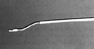
Cranked rod end
In a moment of weakness, I dug a hole in the ballast for the first stool and planted it. Silly boy – from that moment on, I was chief digger and planter. After disappearing to his bench for five minutes with a file and a length of rodding, Peter produced the most amazingly shaped (square to round section and back to square and then to half square, all correctly cranked) rodding end where it attaches to a crank or compensator, so he too was a marked man. Prem Holdaway is chief rodding wire straightener (an absolutely essential task) and solderer of rods to cranks and compensators, as well as helping me in the gardening department with stool height and alignment checking.
Our overall assembly strategy had therefore formulated itself. Having got all the bits we needed in stock, and established a stool, crank and compensator list, these parts could then be soldered up off site, and then passed over to the digging and planting operation. When these finished assemblies were in place in their ground mountings, the rods themselves could be cut and fixed. The final stages would be cosmetic detailing and painting. By planning a little ahead, we attained a reasonable flow of work for everyone. In apportioning the tasks, we spread the load but ensured a consistency of appearance in the finished product, which is as vital to rodding as it is to the trackwork itself.
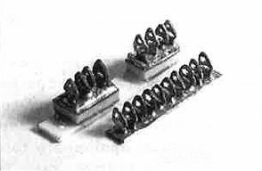
Stools – some of these have been mounted on copperclad bases
We found when making up the Brassmasters' stool etches that our chosen rodding material (0.5mm square section steel, unfortunately no longer available from Scalefour Stores, but Eileen's Emporium does an equivalent in brass) was a very tight fit heightwise between the wire sizes recommended by the Brassmasters' instructions for the top and bottom stool rollers. We eventually used 12 thou (guitar string) steel for the bottom roller, superglued in place, and 6 thou brass wire in the top hole to secure the rod in the stool. Care was taken to ensure that no superglue got on top of the 12 thou wire to reduce the vertical space the rod would take up inside the stool. Getting the etches aligned exactly when making up the stools for more than two or three rods is difficult, and after mumblings of discontent from the installation gang, Tony drilled out the top holes of the made-up stools with a No 77 (0.45mm) drill in order to squeeze a bit more space to wiggle the 6 thou top wire in over the rods. Later, for the really long stool assemblies, a No 76 (0.5mm) drill was used. The made-up stools are surprisingly fragile and very prone to damage, prior to rod fitting, once in place on the layout. Our longest stools are 9 rodders (that's 10 stool sides), which is more than the maximum possible on the stoolbase supplied on the Brassmasters' etch, so Tony made these 'long specials' by fretting out new bases, paying particular attention to maintaining the correct rodding pitch over the whole length of the stoolbase – nothing looks worse than irregularly pitched rods.
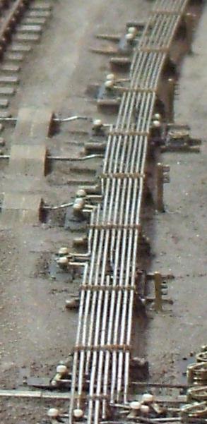
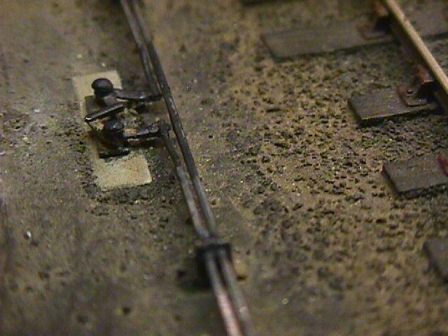
Determining crank positions by intersecting dummy rods
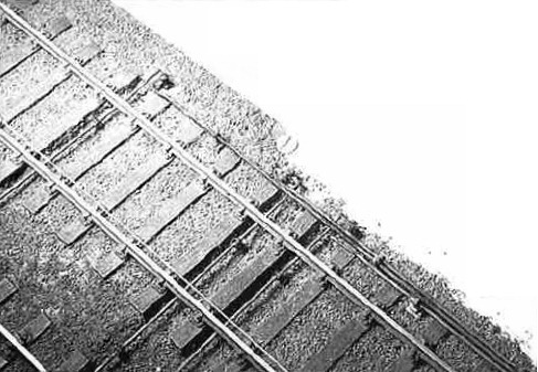
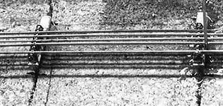
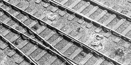
Below-rail rodding (with a stretched cotton alignment marker on top of the nearside rail)
When planting the stools, I often dug quite a deep hole in our ballast (3/16" of cork, in most places) and mounted the stool base and its copperclad sub-base onto a further pillar of plasticard, so that the planted stool assembly had a good bedding. The stools were epoxied into the ballast hole, any gaps being made good later with very fine ballast material, and I think Prem and I managed about a maximum of five stools at one go, spending the glue-setting time ensuring that they remained square in all planes and at the correct height. As aids to stool location and alignment, much use was made of stretched cotton threads for the straight runs, and 22 or 24 thou steel wire (guitar strings again) for the curved runs. Occasionally I used the guitar strings as dummy rods to hold the stools in the right place while the epoxy was setting around the stool base pillar. The rod height convention we adopted was to make the tip of the Brassmasters' stoolsides level with the top of the railhead, and this was simply achieved by using a straight edge or square resting on the rails. Some prototype rod runs are set below the height we selected as our datum, some above, but I think we achieved the right balance considering that many of our rods had to be cranked to run underneath the rails, and we wanted a minimum 0.5mm clearance to prevent any possibility of electrical shorts developing – there are a number of stools set in the 4' and 6' ways (as per the prototype) to ensure the rodding stays at its intended low level underneath the rail.
To lay rods under the rails, trenches had to be dug in the ballast – this was vexing work, especially under pointwork, and even more galling because the painting of the trackwork had been substantially finished. When the cutting of the trenches was completed, they had then to be partially re-ballasted and repainted. There's another lesson for us: we didn't plan ahead well enough. Thankfully we weren't using real granite for the ballast (we use Woodlands Scenics fine grey mica).
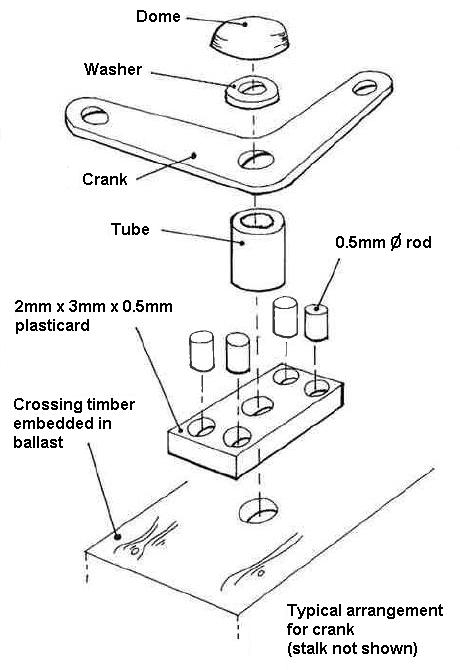
Typical arrangement for crank
For the cranks, we decided against using the Brassmasters' crank base plates (they are so huge), and Tony soldered the crank etches to 18 thou nickel-silver wire, sufficient in length to form a mounting stalk. Small washers (supplied on the etch) and tiny sections of tubing (cut by Peter with a jeweller's tube cutter) above and below the crank respectively were fitted to improve the appearance and control the height of the crank above its base. By laying in intersecting dummy rods in the relevant stools, the pivot axis of each crank could be determined and drilled into the baseboard. I then set wooden bearer bases (stained sleeper strip) into apertures cut into the ballast over the drilled positions. I made new crank bases from 2mm x 3mm pieces of 20 thou black plasticard, into each corner of which was set 20 thou plastic rod, trimmed for height, to represent the crankbase boltheads. These bases are tiny, and it takes a second look to see what they are, but we wanted to have a representation of what on the prototype is quite a substantial casting. The crankstalk was then set through the middle of this crankbase and the whole thing respotted onto the wooden bearer: all this was fiddly and time-consuming work, and the cause of much cussing from me if the resulting crank position didn't line up exactly with the dummy rods, necessitating a re-drill and re-position. Double and triple crankstalks presented more problems, with different crankbase dimensions, and care had to be taken to set the crankstalks at different heights to allow room for the rod-soldering gang to subsequently attach the final rods to the tips of cranks set on the lower levels. I pre-tinned the cranktips to ease their unenviable task. I also found that the curved cranks on the Brassmasters' etch gave slightly different throw lengths compared to the straight ones, and some filing was needed to get the multistalk assemblies lined up to keep to the required rod pitch. The Brassmasters' etch gives three sizes of crank; the majority of ours are the medium size, this we felt being most consistent with the compensator arm length, although the small size cranks were used in some of the pointlock runs. The cranks making the final connection to the point blade stretcher bars are of the 'adjuster' variety, and these are supplied on the Brassmasters' etch.
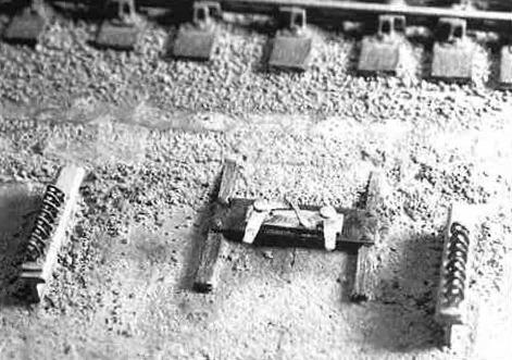
Tony made all the compensators, and these were mounted on brass bases cut down from the Brassmasters' offerings: the size we chose was 8.5mm x 2.5mm. Each compensator arm etch had its middle section chopped out and put back together again so as to produce a prototypically 'closed' or 'open' compensator, as appropriate to its function in its rodding run. The compensator brass base was then mounted on a 10 thou black plasticard subplate (15mm x 5mm for a single compensator), with 20 thou boltheads at each corner, and laid as described for the crankstalks. In the 'ditch run' adjacent to the platelayers' hut, the compensator bases are set on top of massive concrete stools, which Peter and I shaped and filed up from lumps of Milliput.
The stools in the ditch run and the big run adjacent to the box are outside the ballast perimeter, and are mounted on T-section brass which Tony made from American-sourced 3/32" x 3/16" (4.8mm x 2.4mm to us normal folk) heavy I-section obtained from Eileen's Emporium. This T-section was set into slots cut into the baseboard surface with a razor saw.
Compensator mounted on concrete stool – photo: Tony Wilkins
 |
T-section concrete stool support set into baseboard with dummy rods | 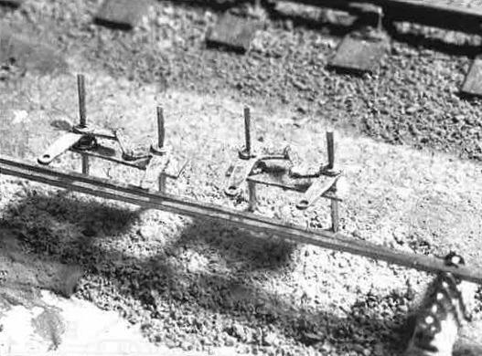 Locating compensator stalks |
|
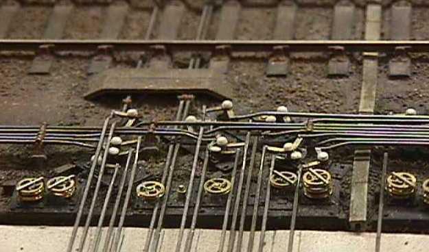
Dummy rod alignments in the signal box run |
 Stool alignment with dummy rods |
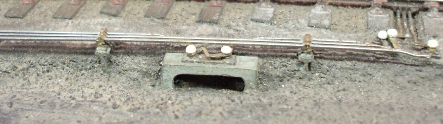
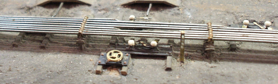
Compensator in signal box run awaiting final rods
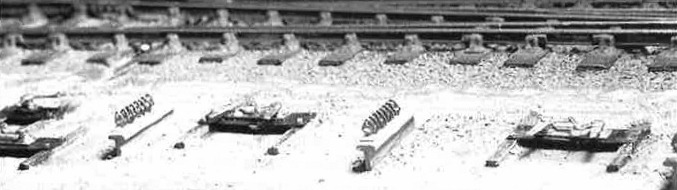
Finished cranks and stools await their rods
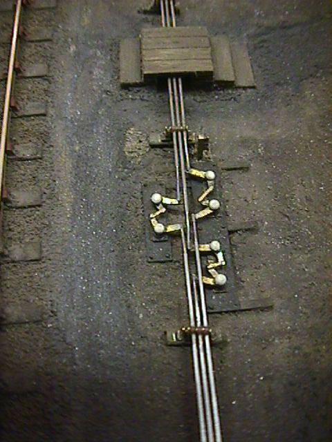
In the signal box run, all the cranks and compensators have their sub-bases set off the baseboard deck with 10 thou black plasticard platework studded onto wooden bearers. These bearers (I used strips approx 1.5mm wide) are partially or in some cases wholly embedded into the ashground, with the studding being the usual 20 thou plastic rod to represent the boltheads securing the platework to the bearers. The dimensions of the platework were guesstimated from photos, but these vary according to how many cranks and compensators are required to locate within a given space. The setting of the cranks immediately in front of the signal box proved to be a bit of a nightmare, as the space is so restricted, and we had to resort (as we suspect the prototype did in such a location) to an extra rod height to get them all into the box. Photos of rodding practices immediately in front of boxes are very elusive, boarding over being the prototype norm.
Having set all the stools, cranks and compensators in position where they should be in a run, any groundwork (reballasting, ashwork, etc) in the immediate vicinity of the rodding run was attended to, and then the rod straightening, cutting, shaping and soldering crew (Peter and Prem) would get to work. Cutting the exact length of rod allowing for the necessary cranking at its ends is a bit of a trial and error process, especially on the long runs, and it is essential that the finished rod can lay true along its length, pre-curved where necessary, without the need for additional constraint – any height discrepancies across the runs or rods straying from their exact pitch are very noticeable. Tiny pieces of 6 thou brass wire were manoeuvred through the top hole of the stools to secure the rod. We have experienced some slight temperature expansion problems, and this is being cured in the longer runs by splitting the rods with sliding expansion fits, the incision of the split being supported by a stool.
Soldering the steel rod (pre-tinning is essential) to the crank is difficult, and although Prem is deft and quick with a hot iron, some of my plastic boltheads just a millimetre or so away from the irontip have understandably gone back to the great boltmaker in the sky. We aim for a reasonable survival rate. A greater problem has been the occasional crank detaching itself from its stalk, if the iron dwells a fraction of a second too long. I'm critical, but you wouldn't catch me attempting to do this difficult soldering job.
At baseboard joints, the rods were supported on brass T-pegs set into the baseboard, the pegs being set as close to the baseboard edge as we dare. Prem made a rod comb gauge from a piece of scrap brass to set and retain the pitch of the rods whilst they were being soldered to the pegs. The brass rod is much easier to solder, but we feel the steel material has the edge in terms of strength and 'non-kinkability'. All soldering of the steel rods was done with a non-acid flux, to minimise any future corrosion problems.
The pièce de résistance on the stools are the top rollers. I had demanded to see something on top of the rods in the gap left between the top of the stool sides, but I was half-hearted in my demand, not really thinking that this was achievable. Lez Zahra, not previously known for having a liking for the mechanical things in life, especially microscopic ones, then proceeded to cut hundreds of minute (and I do mean small) lengths of 0.75mm diameter wire insulation, and then sliced each one open along its axis, and superglued them one by one inside the stool tops over the top of the 6 thou rod-retaining wire. Crank belltops were shaped from 1.5mm diameter plastic rod and superglued to the tops of the cranks. We're not happy with the shape of some of the belltops on the cranks, so these will have to be remade.
Most of the painting of the rodding is being done by Lez – we are aiming for a rust shade on the stools and their rollers, a dusty light grey-brown for the rods, and an off-black for the greased and oiled parts of the compensators and cranks.
Compensator stud and platework, plus T-section stool stands
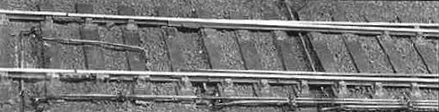
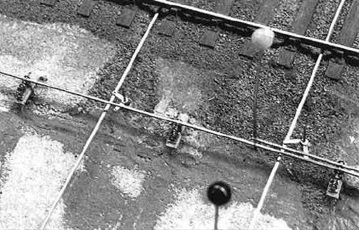
Platform release crossover (tiebars, point lock details and detectors still to be added)
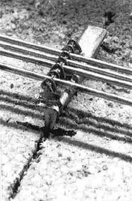
The attachment of rods to compensators and cranks needs some planning in order to get to the attachment point – photo: Tony Wilkins
Painted compensator on a sunken concrete base
|
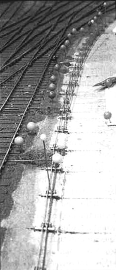
The signal pulleys are from the Brassmasters etches – these pulleys have a half-etch on one side for the groove, and each of our pulleys is therefore two pieces soldered face to face.
The pulleys have top cradles added from flattened wire, although some are missing from the pictures here. |
|
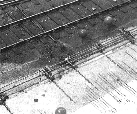
An early stage in planning the front of the signal box, with dummy rods converging
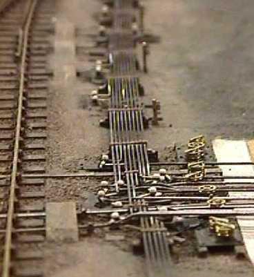
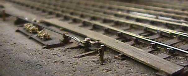
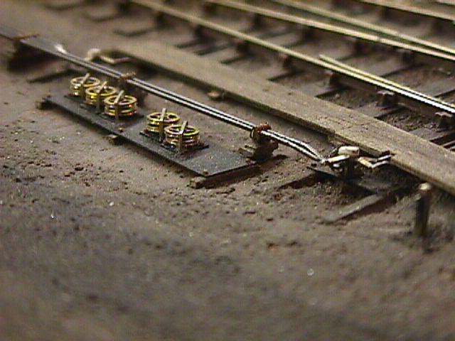
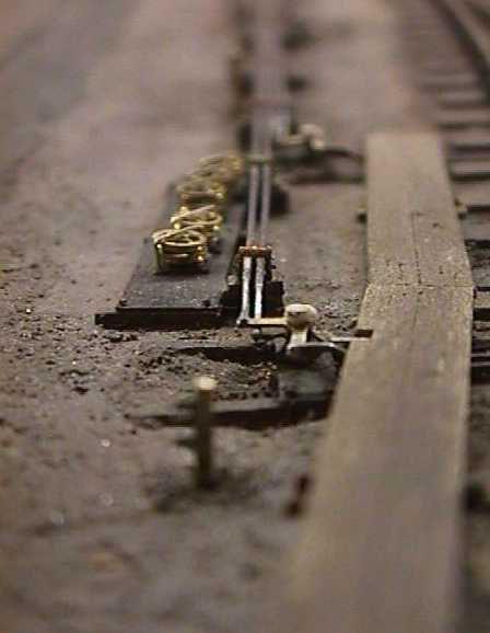
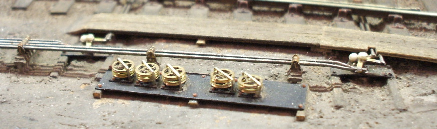
photo: Tony Wilkins
© Russ Elliott
May 1999, updated August 2009 with SN108 description
| Return to top of page | Green Street menu page | Safety, privacy and cookies |