
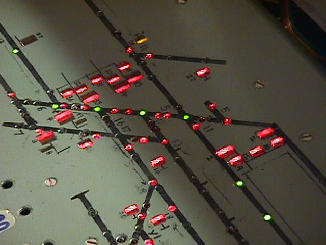
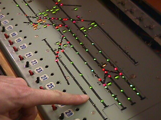
Electrics and controlsSignalman's control panelA few glimpses at part of the signalman's control panel, showing the point and signal levers and their indicators on the track diagram. It's a 40-lever box.We hope to make a much larger mimic diagram above the layout for the drivers to look at so that they don't have to lean over the signalman's shoulder all the time. Interlocking isn't incorporated yet, which is why the picture opposite is very naughty, with all the signals at green. |
|
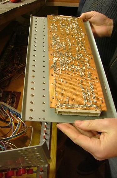
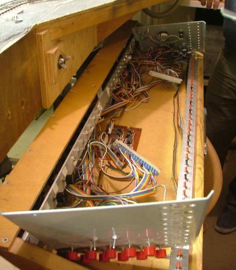
| Two recent pictures taken by James Moorhouse showing the underside of the centre section of the control panel, below left, with its the Veroboard construction, and the connectors at either end. The picture on the right shows the mating connectors, and the wiring to the subsidiary panels, which cater for the Alex Jackson couplers, the block instrument, and the levers for the exchange sidings. | |
|
|
 Board wiring
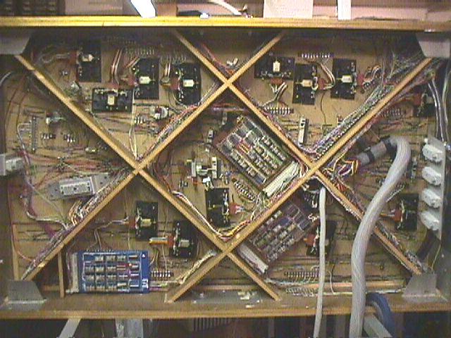
Green Street's electronics are a bit complicated. Here's a picture of the underside of the main baseboard.
Controller plug and socket wiring
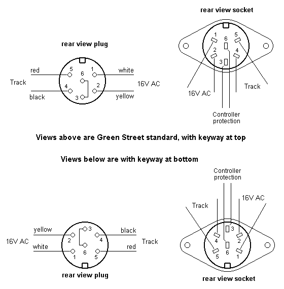 We use 6-pin 270º DIN plugs and sockets for our controllers.
The interlock circuit is intended to prevent more than one controller socket outlet being available to a particular controller.
© Russ Elliott and James Moorhouse
first issued May 1999
baseboard underside pic added January 2011
controller plug and socket diagram added January 2011
| Return to top of page | Green Street menu page | Safety, privacy and cookies |