Fulgurex point motor wiring
by Russ Elliott
Fulgurex point motors are rated at approx 200mA. They tend to be a bit fierce when operated in their official 10 to 14V range, and are quite happy with a more modest voltage.
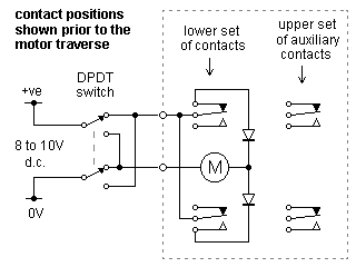
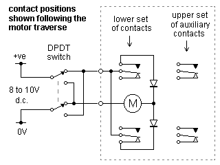
A single potential supply connects via a DPDT switch to the point motor. The point motor will operate irrespective of the polarity of the supply. In the diagrams below however, a particular polarity is used to show how the point motor operates.
|
The lower set of contacts are the limit switches, and cut the supply to the motor when it has finished its traverse. The upper auxiliary set of contacts operate slightly before the lower set.
|
|
|
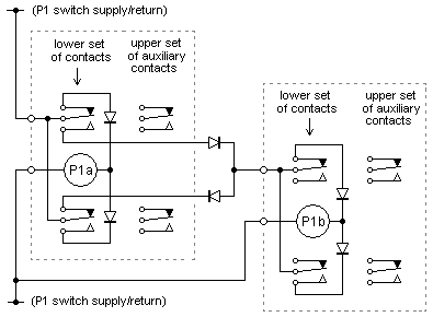
Using a pair of extra diodes, two point motors can be wired up to act sequentially rather than simultaneously from a single DPDT switch. In this particular circuit, P1a always operates first.
|
|
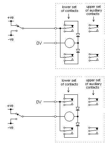
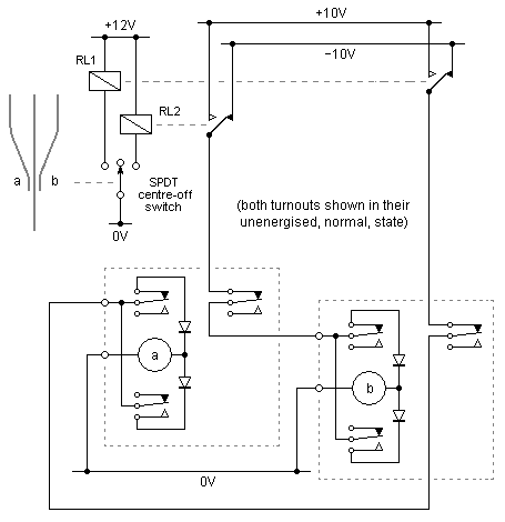
Fulgurex point motors can also be operated on a split potential (+ve/0V/-ve) configuration, to save some wiring between control panel and baseboard.
The switched potential can be applied either to the base of the motor or via the switched set.
|
|
|
For a 3-way turnout with overlapping blade sets, the split potential circuit adjacent will move the blade sets in their correct sequence.
|
|
© Russ Elliott
January 2008
operating explanation added 25 June 2008
split potential diagram added 17 July 2008
3-way circuit added and sequential circuit amended 5 August 2008
|


