This page describes some progress and experiments on induction charging of on-board batteries, and associated radio control |
Users of LiPo batteries should be aware of some potential dangers regarding their use. |
Radio Control – some options
by Ted Scannell
Radio control – why?
On a real railway before the digital revolution, the driver was in physical control of the train, on board the train (although the guard was 'in charge'). Until the arrival of electric trains and locomotives, so was the fuel, the source of power. The locomotive could go anywhere, independent of a power source, run the 'wrong' way through a set of points, and even run round a return loop without causing a standstill through short circuit. Forward was always forward, irrespective of which way round it was on the track. The wheels and axles were solid metal, providing a current path across the rails, enabling a relatively cheap and simple system of track detection, so those interested could tell remotely where a train was.
On board power and radio control allows all these things. And because the power source is on board, there is never an interruption caused by dirty wheels or track surface. In fact there is no need for track at all, save to guide the train.
So why not?
Well, many modellers will have invested lots of time and money in wiring layouts. Some will have been lured by the promises of DCC, and found that they still have to wire their layouts, as well as investing considerably in power supplies and receiver chips.
It isn't easy. It is not possible to open a box, stick it on the track, and it just works. Some level of technical understanding will be required, about the same level as setting up a DCC system, but slightly different thinking.
LiPo battery
The ones on eBay, Gearbest, etc., made in China for quadcopters and drones have a very small internal pcb which controls the charge and discharge rates. This is usually described as a 'safe' battery. A single cell has a nominal 3.7V, and is quickly destroyed if the voltage on the bare cell is pushed to over 4.2V, or discharged below 3V. These have a common connector, and are available in 240mAh to 1000mAh capacities, with a corresponding variation in size.
They have some really good properties, and some very bad ones. A not-so-good one is that they don't weigh much for their volume. Also not so good is that they will not charge properly in series. So if you want to join three in series to get around 12V, they will have to be separated and charged individually. There are 'smart chargers' available, but see 'voltage booster' below.
On the other hand, they put out a constant current until the control circuit switches off. No slowing down as the battery drains, like we're used to with NiCd or NiMh. Another positive is that when disconnected, the charge does not fade over time; one tested lost 0.4V in 6 months.
There are though, great dangers with 'bare' cells. If shorted, they will dump a massive amount of current in a short while, and if not contained, swell up, and give off a noxious fume which may be flammable. Whatever shorted it will get very hot very quickly too, glowing white if it is a wire.
Being positive again, the control circuit allows the battery to be recharged at 5V DC from a variety of sources, induction, regular pickups through a regulator, or USB, and prevents overcharge by switching off at 4.2V. That internal controller has only two wires, so current flow in and out does not need to be switched externally.
LiPo balancing pcb
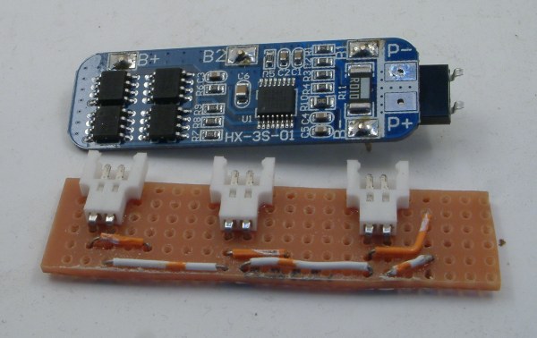
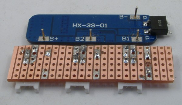
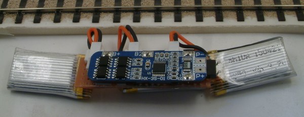
The pcb controls the balance of the charge to the three LiPo batteries attached to the connectors. It requires a 12.6V DC supply to the 'P' inputs to fully charge the batteries, the supply drawing in my testing so far a max of around 20mA. With the bridge it needs 14V AC or DC. Output is 12.7V DC max, (so far!) I have yet to drain it to find out the lowest it will go before switching off.
If any (or all) of the batteries are disconnected and then reconnected, whatever the state of charge, no output will appear until an input is sensed and removed.
The pcb is 50 x 16 x 3mm, but I have added a bridge rectifier to the inputs 'P' which make it a little longer and thicker. The inputs are also outputs, so the top pads are for the line to the Rx.
The connectors on the stripboard came from the USB charger units that came with the battery packs bought on eBay. These are available in 250mA, 350mA, and 650mA capacities, the 350mA shown being about the same width as the pcb and stripboard. The batteries still have their own individual built-in protection circuits, so we are double-safe for the h&s nerds out there.
I am currently paying £1.53 for each of these pcbs on eBay.
Voltage booster
This pcb, labelled icsa004a, uses the MT3608 chip which allows for the input from a single LiPo cell to be boosted to up to 24V at up to 2A. At 37 x 17 x 6mm, it is the same size as a 350mAh 'safe' battery.
To work out the effect on the time the battery can supply, the demand from the motor needs to be calculated. Some draw quite a lot of current, but a typical commercial motor usually draws around 350mA, a coreless around a tenth of that.
To calculate, the motor demand needs to be converted to watts. Watts is V x A, so the commercial motor above at full power and load will need 12 x 0.35, or just over 4W. The battery before the voltage boost delivers at a mean of 3.6V, so the draw on the battery will be 4.2/3.6, or 1.2A. It is therefore reasonable to expect a 350mAh battery to last for 350/1200 hours, or around 20 minutes. But remember, this is at full power and full load.
Charging options
For traction units being converted that already have pickups fitted, they can be used with any normal supply, DC or DCC AC, by installing a bridge rectifier and a Traco 5V regulator. (Shown under the 14XX chassis below.) This can be permanently wired to the battery and will charge it when the internal controller requires it. These regulators are 'switched mode' and do not get hot like older regulators, so do not need a heat sink nor risk melting plastics.
An alternative is to fit a connector for a feed from a USB port, which also provides a 5V DC supply, but of course tethers the unit during charging.
Induction charging is a further option. This is the same technology as the charger for an electric toothbrush. That shown consists of a transmitter coil and pcb, which requires a 10V DC supply. A number of these can be installed with their own supply, or the alternative as shown is fitted with a bridge rectifier and phosphor bronze wire pickups sprung between the rails. The transmitter coil does get warm, up to 45°C, but that is lower, just, than pain level, and is no threat to the models or the track.
The receiver coil needs to be fitted as close as possible to the transmitter, in the case shown just lower than the bottom of the fuel/water tanks on a Class 24. The transmitter coil tested is 1mm above rail level, with an air gap of some 1.5mm, which gives a reasonable rate of charge.
Any combination, or all of the above, can be wired directly to the battery positive conductor in the traction unit, and that to the input connections of the booster pcb.
The battery internal controller will usually limit the charge rate to around 160mA in the batteries tested so far, which offers a guide to the time taken to charge a fully discharged battery, but as they retain charge very well, this is unlikely to be a serious consideration in normal use, unless tethered charging is chosen as the only option.
Radio receiver/controller
There are a number of options on the market, well detailed on The Dead Rail Society
The receiver in the Bachmann Class 24 shown below is a British version, a Deltang Rx61d. These, or the later and recommended Rx62 are available from Micron Radio Control. As pointed out on the Dead Rail Society page, the Deltang website can feel a bit obscure, but lists the many control variables available within the receivers, and good further information is available there.
Bachmann Class 24
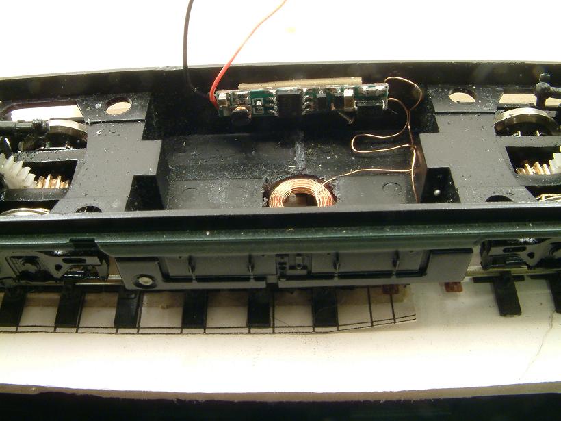
The tanks of this Bachmann Class 24 have been cleaned up inside, and a hole drilled in the centre to allow the receiver coil to be glued in. The receiver pcb fits neatly against the side of the tanks, using double sided tape. The output from this pcb when the receiver coil is over an active transmitter coil is 5V DC at around 160mA, depending on the distance between the coils.
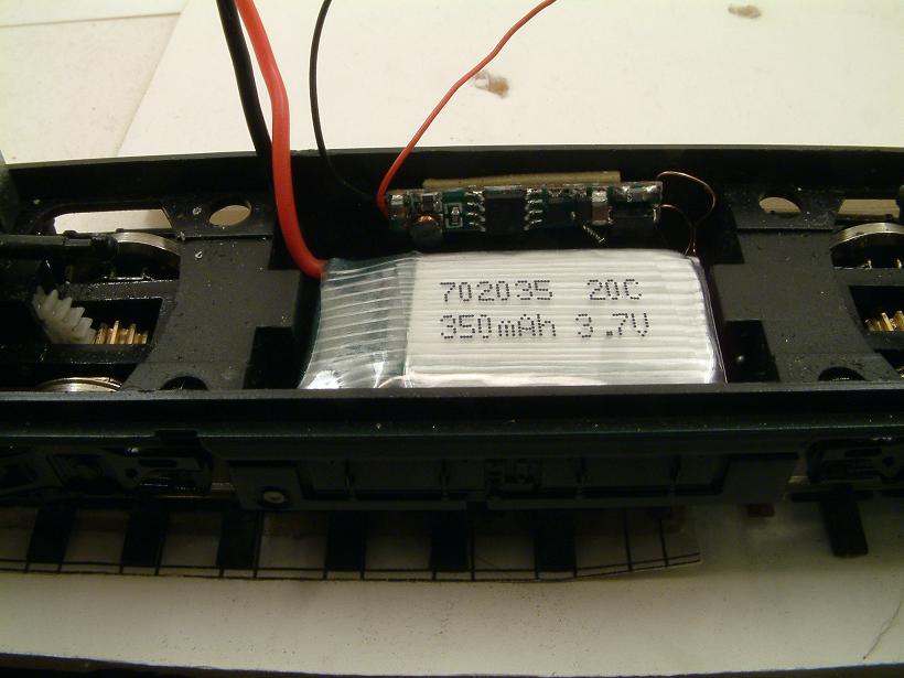
This is the largest Li-Po battery that fits comfortably in the tanks space.
Showing the distance between the transmitter coil in the track, and the receiver in the loco. This will be a little closer when the loco is weighted.
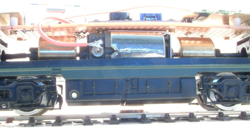
The original motor mounted above the battery, held in place by the stripboard which replaces the centre of the original weight and motor mount. This modification allows space above for the radio receiver, voltage booster circuit and even a battery for later locos such as the Class 25s which had the water tanks removed. Some extra weight could be added if required, but this loco is fitted with Penbits sprung bogies, so compensating for the loss of weight with more efficient traction.
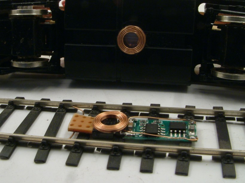
Another view of the transmitter coil in the track, and the receiver in the loco.
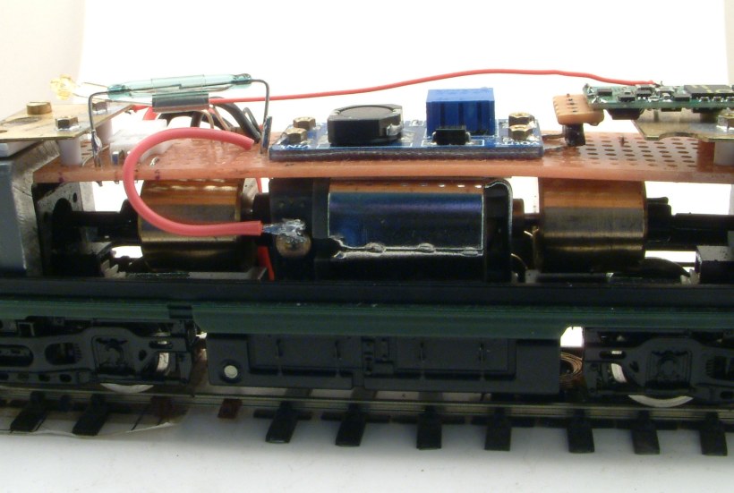
Populated stripboard, from left to right – Indicator LED, temporary, to show when the receiver coil is receiving; Magnetic latching reed switch, which isolates the next pcb, the voltage booster circuit. The white block under the reed is the battery connector. Then the voltage booster pcb, which supplies 12V power to the radio receiver, in this case a DT Rx61d-22.
Fitting a 14xx 0-4-2T
Though there may have been room for the induction receiver coil underneath, there is no space for the pcb unless I throw some of the weights out. Not really an option if I want it to pull anything more than one autocoach. This option demonstrates that induction isn't necessary, just desirable in some circumstances; there is even a 12V option coming, now that I have had a better look at what is available on eBay.
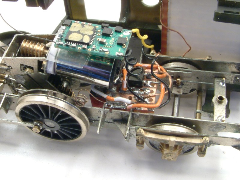
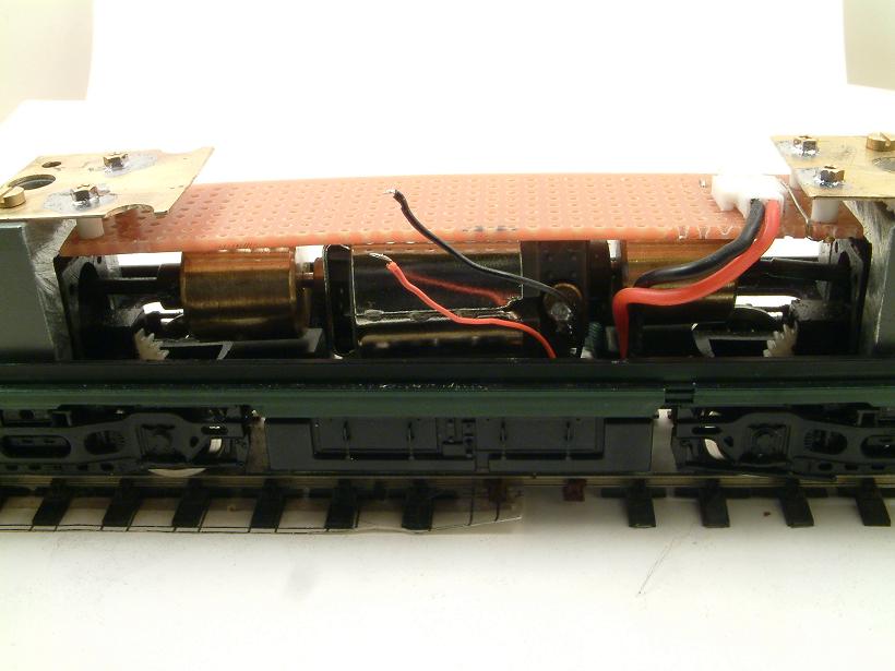
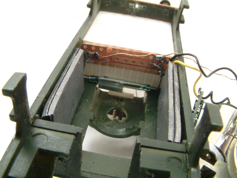
This shows the motor, a 10x16 3.7V coreless, attached (superglue!) to a 60thou pad of styrene drilled and tapped 12BA in order to attach it to the High Level gearbox. Above it is fixed, via a pair of 30swg lengths of phosphor-bronze wire, the Rx63a-22 DT receiver.
The stripboard between the frames carries a pair of pickups resting on the rear drivers only – if the collection is intermittent it doesn't matter, as the battery maintains the power to the receiver and the motor, the collection only serving to charge the battery.
The pickups supply the bridge rectifier seen on the stripboard, ensuring that the polarity of supply from the track is irrelevant, and can be a.c. from a DCC power source.
The chassis suspension features a 'live beam', and is illustrated on this page.
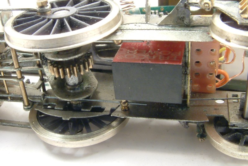
The view from underneath shows the voltage regulator between the frames, where the ashpan would be. This is superglued to a frame crossmember, and soldered into the stripboard. This ensures that no more than 5 volts is supplied to the battery control circuit board.
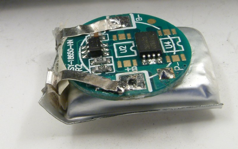
The battery in this case is of 135mA capacity from Plantraco, and since it comes as a 'bare' cell it is protected from over charge or discharge by a control circuit. A large variety of add-on control circuits are available on eBay.
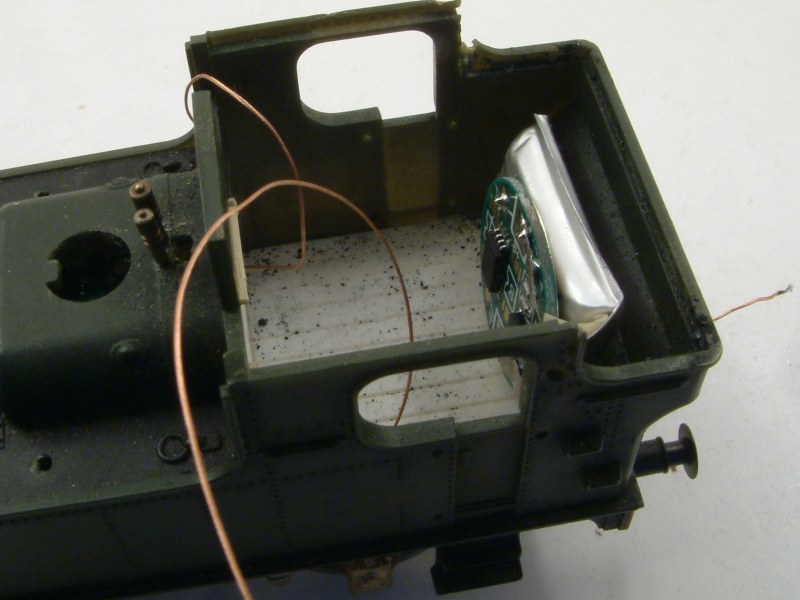
The power package fits neatly in the very small bunker in the Collett tank loco.
This piece of stripboard carries a latching reed switch, wired between the common input from the regulator/battery positive and the supply to the receiver. Some sort of switch is required to isolate the battery from any load, however small, to prevent unwanted discharge of the battery.
© Ted Scannell
12 April 2017
updated 16 April 2017
LiPo balancing pcb added 10 June 2017
| Return to top of page | Safety, privacy and cookies |